Conveying mechanism used for stepwise-type all-dimensional valve cleaning machine

A conveying mechanism, a comprehensive technology, applied in the direction of conveyors, transportation and packaging, cleaning methods and appliances, etc., can solve the problems that the automatic cleaning or cleaning of the workpiece cannot be realized, the cleaning is not thorough, and the automatic transmission or rotation of the cleaned workpiece cannot be realized. Achieve the effect of avoiding incomplete cleaning and ensuring the cleaning effect

Active Publication Date: 2015-02-25
安徽宝辉清洗设备制造有限公司
View PDF6 Cites 9 Cited by
  • Summary
  • Abstract
  • Description
  • Claims
  • Application Information

AI Technical Summary

Problems solved by technology

[0004] The purpose of the present invention is to provide a conveying mechanism for a step-by-step all-round valve body cleaning machine to solve the problem of low production efficiency caused by manual conveying and cleaning of workpieces in th

Method used


Image

  • Conveying mechanism used for stepwise-type all-dimensional valve cleaning machine
  • Conveying mechanism used for stepwise-type all-dimensional valve cleaning machine
  • Conveying mechanism used for stepwise-type all-dimensional valve cleaning machine

Examples


Embodiment Construction

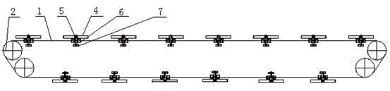
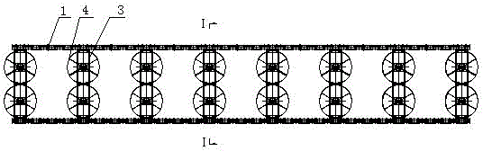
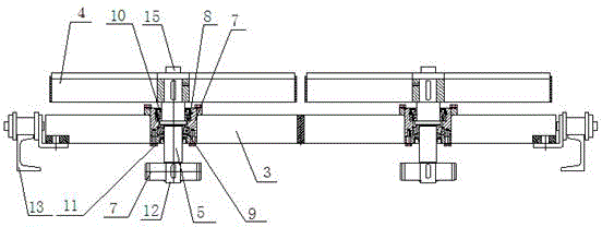
[0024] Preferred embodiments of the present invention will be described in detail below in conjunction with the accompanying drawings.

[0025] Such as figure 1 , figure 2 and image 3 As shown, this embodiment provides a conveying mechanism for a step-by-step all-round valve body cleaning machine, including a conveying chain 1, several guide gears 2, several pallets 4 for carrying workpieces, and a mechanism for fixing bearing seats 6. Several supporting plates 3, rotating shafts 5, bearing blocks 6 and rotating gears 7, the transmission chain 1 meshes with the guide gear 2, the two ends of the supporting plates 3 are respectively connected with the transmitting chain 1, and the middle part of the supporting plates 3 A bearing seat 6 is provided, and a bearing one 8 and a bearing two 9 are sequentially arranged in the bearing seat 6, and the rotating shaft 5 passes through the tray 4, the bearing one 8, the bearing two 9, the rotating gear 7 in sequence, and the rotati...


PUM


Abstract

The invention provides a conveying machine used for a stepwise-type all-dimensional valve cleaning machine which comprises a transmission chain, a plurality of guide gears, a plurality of trays used for bearing workpieces, a plurality of support plates used for fixing bearing blocks, rotating shafts, the bearing blocks and rotating gears. The transmission chain is meshed with the guide gears, two ends of the support plates are respectively connected with the transmission chain, the middle portion of each support plate is provided with one bearing block, a first bearing and a second bearing are sequentially arranged in each bearing block, each rotating shaft penetrates the corresponding tray, first baring, second bearing and rotating gear in sequence, and each rotating shaft is meshed with a rack used for driving each gear to rotate. The transmission chain is driven to rotate through the guide gears so as to enable the support plates to move on the chain, and the trays drive the workpieces to move to be conveyed. The gears rotate on the racks to drive a base and a tooling plate, so that the workpieces fixed on the tooling plate can be automatically and all-dimensionally cleaned, thorough cleaning is guaranteed, and dead corners for cleaning of the workpieces are removed.

Description

technical field [0001] The invention relates to a conveying mechanism for a step-by-step omnidirectional valve body cleaning machine. Background technique [0002] In the process of cleaning the workpiece, it is necessary to clean the workpiece in all directions, so as to avoid the residue of cleaning dead angle and affect the cleaning effect. However, in the existing cleaning process, the manual transportation and cleaning of the workpieces causes the problem of low production efficiency, and because the automatic transmission or rotation of the cleaned workpieces cannot be realized, the automatic cleaning or cleaning of the workpieces cannot be realized. Thorough problem. [0003] How to realize the automatic transmission and automatic rotation of the workpiece is a problem that should be considered and solved in the process of cleaning the workpiece. Contents of the invention [0004] The purpose of the present invention is to provide a conveying mechanism for ...

Claims


Application Information

Patent Timeline
IPC IPC(8): B65G17/00B65G17/48B08B13/00
CPCB65G17/12B65G17/48B65G2201/02
Inventor 杨锡威
Owner 安徽宝辉清洗设备制造有限公司
Why Eureka
Try Eureka