
A sewing machine mop wheel device

A cloth mopping wheel and sewing machine technology, which is applied in the field of sewing machines, can solve the problems of insufficient uniformity of stitches, inconsistent stitches, influence on aesthetics, etc., and achieve the effects of good mopping effect, uniform stitches and good stability.

Inactive Publication Date: 2016-09-07
林日长
View PDF6 Cites 0 Cited by
  • Summary
  • Abstract
  • Description
  • Claims
  • Application Information

AI Technical Summary

Problems solved by technology

[0002] When the sewing machine is working, the teeth under the presser foot cooperate with the presser foot to realize the cloth feeding. At present, there are situations such as slippage in this cloth feeding method, which makes the stitches out of sewing inconsistent and affects the aesthetics. For some special fabrics, there is a cloth feeding problem. Because of the difficult problem, it can't even work normally; in addition, the existing sewing machines mainly rely on manual control when sewing arcs, so that the arcs cannot be guaranteed to be smooth and uniform, and the stitches are not uniform enough; After direct sewing to the end, the suture line at the junction needs to be removed during longitudinal sewing, which increases the sewing efficiency of the reduced process. At this time, it is necessary to use jumper technology to avoid similar situations.
[0003] In addition, the interior of the existing sewing machine is provided with a built-in presser foot lifting mechanism. For example, the Chinese patent announcement No. CN203159869U discloses a built-in automatic presser foot lifting mechanism for sewing machines, which includes the following parts: a casing, and the casing includes a column There is a cavity in the column part; the linear driver is fixedly installed in the cavity, and the linear driver includes a draw bar that can reciprocate in a straight line, and a rear end of a rear lever and an end of the draw bar The front end of the rear lever includes two pin holes, wherein the first front pin hole is rotatably connected to the casing through a pin shaft, and the distance from the rear end of the rear lever to the first front pin hole is greater than the distance from the second front pin hole to the The distance between the first front pin hole, the front lever includes three pin holes, the first pin hole is rotatably connected to the casing through the pin shaft; the second pin hole is hinged with the presser foot lifting plate; The second front pin hole of the rear lever is hinged, and the front end of the pull rod is hinged with the third pin hole of the front lever; this mechanism sets the presser foot lifting mechanism inside the housing, and uses the lever to amplify the force of the linear drive and play a role The reversing effect makes the structure more compact and more reasonable, but once the automatic presser foot lifting mechanism breaks down, the sewing machine cannot work normally, which brings inconvenience to production, and its reliability needs to be improved.

Method used


Image

  • A sewing machine mop wheel device
  • A sewing machine mop wheel device
  • A sewing machine mop wheel device

Examples


Embodiment Construction

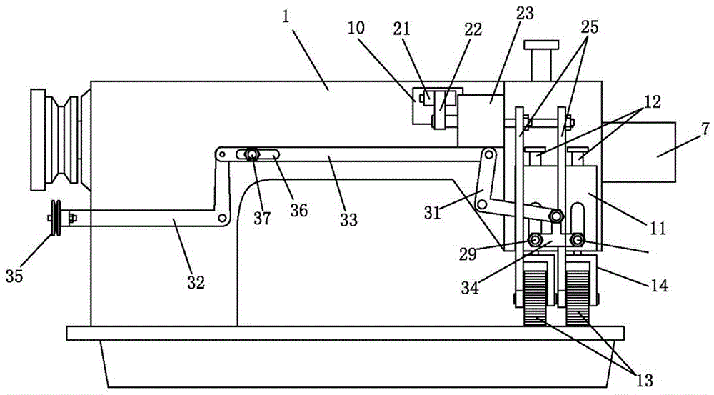
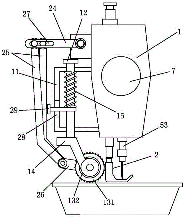
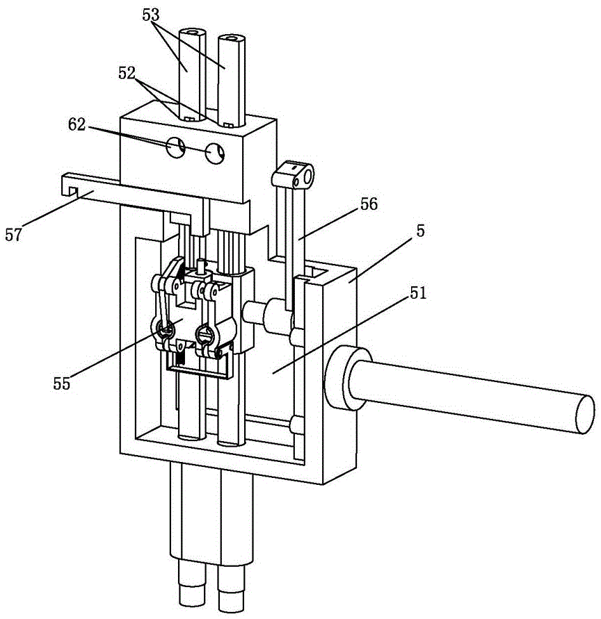
[0019] Such as Figure 1-8 As shown, a sewing machine mop wheel device includes a sewing machine head 1 and a presser foot 2, and a mop wheel device is arranged on the back of the sewing machine head, and the mop wheel device includes a box body 11, a mop wheel pressing bar 12, a single To the mop wheel 13 and the link mechanism, the box body 11 is fixedly connected to the back of the sewing machine head 1, and two mop wheel pressure bars 12 arranged in parallel pass through the box body 11 from top to bottom, and each mop wheel presses The lower ends of the rods 12 are provided with mop wheel brackets 14, and each mop wheel bracket 14 is provided with a one-way mop wheel 13, and a spring 15 is sleeved on the mop wheel pressure rod 12, and the spring 15 is accommodated in the box 11 Apply downward pressure on the mop wheel pressure bar 12; the one-way mop wheel includes a mop gear 131 and a one-way ratchet 132, the mop gear 131 is sleeved on the one-way ratchet 132, and the on...


PUM


Abstract

The invention relates to a cloth dragging wheel device of a sewing machine. Two sets of cloth dragging gears are arranged behind a presser foot and connected to one-way ratchet wheels in a sleeving mode. The one-way ratchet wheels are linked with a main shaft in a sewing machine head through connection rod mechanisms. The presser foot and stitches operate synchronously. The cloth dragging wheel device of the sewing machine has the advantages of being stable in operation and good in cloth dragging effect. The rotation amplitudes of the two sets of cloth dragging gears are different every time by adjusting the positions of the two sets of connection rod mechanisms, and the left cloth dragging gear and the right cloth dragging gears are not balanced in cloth dragging, so that cloth is bent towards one side, and the arc sewing function is achieved.

Description

technical field [0001] The invention relates to sewing machine technology, in particular to a cloth mopping wheel device for a sewing machine. Background technique [0002] When the sewing machine is working, the teeth under the presser foot cooperate with the presser foot to realize the cloth feeding. At present, there are situations such as slippage in this cloth feeding method, which makes the stitches out of sewing inconsistent and affects the aesthetics. For some special fabrics, there is a cloth feeding problem. Because of the difficult problem, it can't even work normally; in addition, the existing sewing machines mainly rely on manual control when sewing arcs, so that the arcs cannot be guaranteed to be smooth and uniform, and the stitches are not uniform enough; After direct stitching to the end, the stitching thread at the junction needs to be removed during longitudinal stitching, which increases the sewing efficiency of the reduced process. At this time, it is ne...

Claims


Application Information

Patent Timeline
Patent Type & Authority Patents(China)
IPC IPC(8): D05B27/10D05B55/02D05B57/02
CPCD05B3/025D05B3/04D05B27/10D05B55/02D05B57/02
Inventor 林日长
Owner 林日长
Learn More