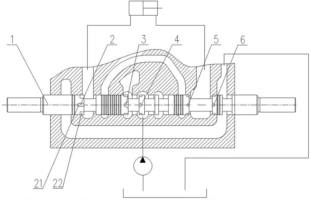
Hydraulic multi-way valve spool
A multi-way valve and spool technology, applied in the direction of valve details, valve devices, fluid pressure actuators, etc., can solve the problems of reduced work efficiency, difficulty in speed regulation range and precise control of working devices, etc., to improve precise positioning, The effect of avoiding shock phenomenon and smooth motion, improving micromanipulation performance and precise positioning
- Summary
- Abstract
- Description
- Claims
- Application Information
AI Technical Summary
Problems solved by technology
Method used
Image

Examples
Embodiment 1
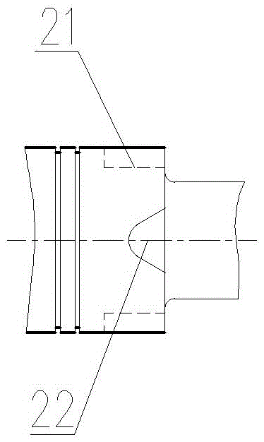
[0023] Such as figure 2 As shown, the auxiliary throttling groove 22 is a triangular throttling groove, and the inner top adopts a circular arc transition.
Embodiment 2
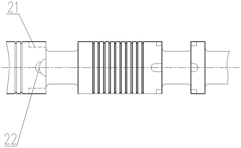
[0025] Such as image 3 As shown, the auxiliary throttling groove 22 is formed by stacking two semicircular throttling grooves.
Embodiment 3
[0027] Such as Figure 4 As shown, the auxiliary throttling groove 22 is an elongated groove with a semicircular inner end, and the depth of the elongated groove gradually increases. The auxiliary throttling groove 22 may also be directly a semicircular throttling groove.
[0028] Through simulation calculation and actual test verification, the present invention provides a variety of combinations of basic throttling grooves 21 and auxiliary throttling grooves 22 on the multi-way valve spool body 1, through auxiliary throttling grooves with different throttling areas and different throttling lengths. The grooves 22 are combined to achieve a proportional change in the flow area of the spool and the displacement of the spool, thereby adjusting the flow and pressure entering the valve port, improving the micro-motion performance of the loader working device and the precise positioning of the working device.
[0029] The present invention only needs to be on the first throttle g...
PUM
 Abstract
Description
Claims
Application Information
 - R&D
- Intellectual Property
- Life Sciences
- Materials
- Tech Scout
- Unparalleled Data Quality
- Higher Quality Content
- 60% Fewer Hallucinations
Browse by: Latest US Patents, China's latest patents, Technical Efficacy Thesaurus, Application Domain, Technology Topic, Popular Technical Reports.
© 2025 PatSnap. All rights reserved.Legal|Privacy policy|Modern Slavery Act Transparency Statement|Sitemap|About US| Contact US: help@patsnap.com