A boom luffing hydraulic system and a crane

A hydraulic system and boom technology, applied in the field of construction machinery, can solve the problems of violent shaking of the boom, affecting the control stability and fretting.

Active Publication Date: 2017-06-30
ZHEJIANG SANY EQUIP
View PDF11 Cites 0 Cited by
  • Summary
  • Abstract
  • Description
  • Claims
  • Application Information

AI Technical Summary

Problems solved by technology

[0003] In view of this, the present invention proposes a jib luffing hydraulic system and a crane to solve the problem that the jib often shakes violently during the jib lowering process, seriously affecting the control stability and micro-movement

Method used


Image

  • A boom luffing hydraulic system and a crane

Examples


Embodiment Construction

[0020] It should be noted that, in the case of no conflict, the embodiments of the present invention and the features in the embodiments can be combined with each other. The present invention will be described in detail below with reference to the accompanying drawings and examples.

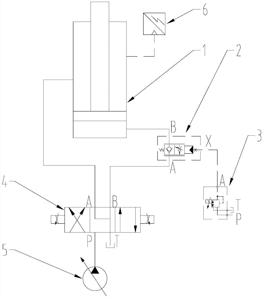
[0021] Combine below figure 1 , the preferred embodiment of the present invention will be further described in detail. The boom luffing hydraulic system in this preferred embodiment, one is to solve the problem that the boom often shakes violently during the lowering process of the boom, which seriously affects the control stability and micro Mobility issue.

[0022] Such as figure 1 As shown, the jib luffing hydraulic system specifically includes: the main pump 5, the main valve 4, the luffing cylinder 1, the fuel tank, the first oil circuit, the second oil circuit, the first oil circuit and the first cavity of the luffing cylinder 1 The oil port is connected, the second oil circuit is connec...


PUM


Abstract

The invention discloses a boom luffing hydraulic system, which comprises a main pump, a main valve, an luffing oil cylinder, a first oil passage and a second oil passage, the first oil passage is connected with the oil port of the first chamber of the luffing oil cylinder, The second oil circuit is connected to the oil port of the second cavity of the luffing cylinder, the first oil circuit is connected to the first working oil port of the main valve, the second oil circuit is connected to the second working oil port of the main valve, and the main pump It is connected with the oil inlet of the main valve, and a pressure control valve is arranged in the first oil circuit. It also includes a servo pump and a servo oil circuit. The servo pump supplies oil to the servo oil circuit. The servo oil circuit is connected to the pilot oil port of the pressure control valve. A hydraulic valve is arranged in the servo oil circuit, and the hydraulic valve controls the opening of the pressure control valve. Spend. The invention solves the shaking of the boom caused by the frequent opening and closing of the balance valve in the past, and improves the stability and micro-movement of the boom luffing control.

Description

technical field [0001] The invention relates to the field of engineering machinery, in particular to a boom luffing hydraulic system and a crane. Background technique [0002] In the boom luffing operation of construction machinery, such as in truck cranes, the actuator is usually a luffing cylinder. In the boom drop operation, the boom lowering generally adopts hydraulic closed-loop control, that is, the balance of the large chamber installation of the luffing cylinder The valve opens and the oil source comes from the small cavity. However, in practical applications, it will be found that due to different loads and different angles of the boom, problems such as violent shaking of the boom and poor fretting often occur during the lowering of the boom. The reason is that the opening oil source of the balance valve comes from the small cavity. During the lowering process, the output flow of the main pump goes to the small cavity of the luffing cylinder and the pilot cavity of...

Claims


Application Information

Patent Timeline
Patent Type & Authority Patents(China)
IPC IPC(8): B66C23/82B66C13/20F15B13/02
CPCB66C13/20B66C23/82F15B11/08F15B2211/205F15B2211/505
Inventor 齐芳朱安宁
Owner ZHEJIANG SANY EQUIP
Why Eureka
Try Eureka