Check patentability & draft patents in minutes with Patsnap Eureka AI!

Touch display screen driving circuit and method

A technology for a touch display screen and a driving method, which is applied in electrical digital data processing, input/output process of data processing, instruments, etc., and can solve the problems of increased power consumption in the mutual capacitive scanning method, etc.

Active Publication Date: 2015-02-25
HEFEI XINSHENG OPTOELECTRONICS TECH CO LTD +1
View PDF5 Cites 16 Cited by
  • Summary
  • Abstract
  • Description
  • Claims
  • Application Information

AI Technical Summary

Problems solved by technology

Therefore, compared with the self-capacity scanning method, the power consumption of the mutual capacitance scanning method is greatly increased.

Method used


Image

  • Touch display screen driving circuit and method
  • Touch display screen driving circuit and method
  • Touch display screen driving circuit and method

Examples


Embodiment Construction

[0029] In order to enable those skilled in the art to better understand the concept of the present invention, the concept of the present invention will be further described in detail below with reference to the accompanying drawings and specific embodiments.

[0030] Figure 4 A flowchart of a driving method for a touch display screen according to an embodiment of the present invention is shown.

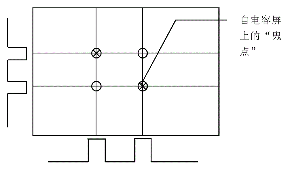
[0031] reference Figure 4 Unlike the driving method in the prior art, before scanning the touch display screen, the number of touch points is first sensed. When the number of sensed touch points is only one, the touch display screen can be driven and scanned in a self-capacitive scanning mode; when the number of sensed touch points is multiple, the Scanning mode scans the touch screen.

[0032] According to the driving method of the present invention, when a user touches with a single finger, it is possible to avoid using a mutual capacitive scanning mode with higher power consumption to ...


PUM


Abstract

The invention discloses a touch display screen driving method and circuit. The driving method comprises the first step of sensing the number of touch points, the second step of conducting driving scanning in a self-capacitive scanning mode when it is sensed that the number of the touch point is one, and the third step of conducting driving scanning in a mutual-capacitive scanning mode when multiple touch points are sensed.

Description

Technical field [0001] The present invention relates to a driving circuit and a driving method for a touch display screen, and in particular to a driving circuit and a driving method for a touch display screen that can switch between different scanning modes according to the number of touch points Drive method. Background technique [0002] Touch screens are increasingly used in personal portable electronic devices such as smart phones due to their superior sensitivity, multi-touch function, and direct finger operation. [0003] The touch screen can include two types: self-capacitance screen and mutual-capacitance screen. The self-capacitance screen uses transparent conductive materials such as indium tin oxide (ITO) on the glass surface to make an array of horizontal electrodes and vertical electrodes. The so-called self-capacitance, that is, the capacitance of the electrode to the ground, is formed between these horizontal and vertical electrodes and the ground. When the user'...

Claims


Application Information

Patent Timeline
Patent Type & Authority Applications(China)
IPC IPC(8): G06F3/044
CPCG06F3/044G06F3/042G06F2203/04104G06F3/041662
Inventor 腾海建郭言文
Owner HEFEI XINSHENG OPTOELECTRONICS TECH CO LTD
Features
  • R&D
  • Intellectual Property
  • Life Sciences
  • Materials
  • Tech Scout
  • Unparalleled Data Quality
  • Higher Quality Content
  • 60% Fewer Hallucinations
Learn More