Flow rate control device

一种流量控制装置、流量调节的技术,应用在阀装置、阀的操作/释放装置、运输和包装等方向,能够解决生产成本增大、工作效率降低、指示精度下降等问题,达到生产成本降低、装配作业高效、指示精度提高的效果

Active Publication Date: 2015-02-25
SMC CORP
View PDF9 Cites 12 Cited by
  • Summary
  • Abstract
  • Description
  • Claims
  • Application Information

AI Technical Summary

Problems solved by technology

[0004] Incidentally, regarding the flow rate control device disclosed in Japanese Laid-Open Patent Publication No. 2011-043196, in order to minimize its size, a structure is provided in which the rotation center of the operation member coincides with that of the indicator ring, and the gear is clamped in the operation Between the member and the indicator ring, however, there is such a structure that when the indicator ring is rotated, the rotational force is transmitted via the two gear members, so that the mechanical meshing error is large, and the problem of decreased indication accuracy occurs
Further, since the number of parts constituting the flow control device is large, there is an increase in production cost, and further, there is a disadvantage that work efficiency at the time of assembly decreases

Method used


Image

  • Flow rate control device
  • Flow rate control device
  • Flow rate control device

Examples


Embodiment Construction

[0037] Preferred embodiments of the flow control device according to the present invention will be described in detail below with reference to the accompanying drawings.

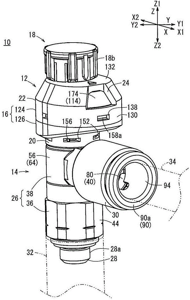
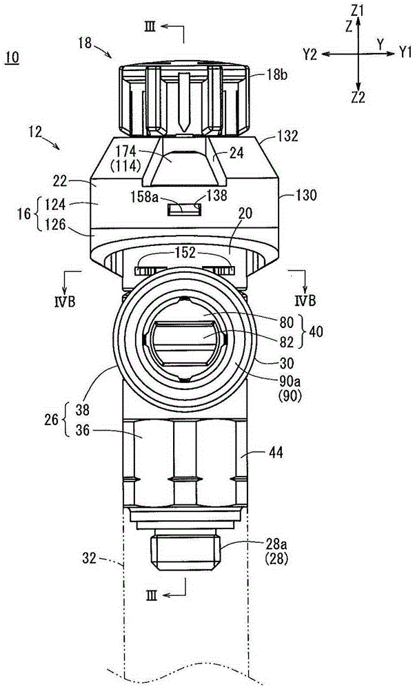
[0038] figure 1 is a perspective view showing the overall structure of the flow control device 10 according to an embodiment of the present invention, and figure 2 yes figure 1 Front view of the flow control device 10. In the following description, based onfigure 1 In the arrow direction shown, the forward and backward directions of the flow control device 10 are also referred to as the X direction (the forward direction is the X1 direction, and the backward direction is the X2 direction), and the left and right directions, namely the width direction, are also referred to as the Y direction. direction (the right direction is the Y1 direction, and the left direction is the Y2 direction), and its height direction is also called the Z direction (the upward direction is the Z1 direction, and the downward dire...


PUM


Abstract

A flow rate control device (10) is provided with a flow rate adjustment indication device (12) for operating the displacement of a needle valve (42) relative to a flow passage (40). The flow rate adjustment indication device (12) is provided with a housing (16), a rotation transmission member (110) which displaces the needle valve (42) by rotational operation, and an annularly shaped indication ring (114) which has a hole (172) through which the rotation transmission member (110) is inserted. The indication ring (114) has graduations (174) which indicate a change in the flow rate of liquid. The engagement of the engagement section (122) of the needle valve (42) displaces the indication ring (114) in the circumferential direction and changes the position of the graduations (174).

Description

technical field [0001] The present invention relates to a flow control device, in which the flow rate of fluid flowing through the inside thereof is controlled, and a change in the flow rate of the fluid caused by a user's operation is indicated. Background technique [0002] In the conduit through which a fluid such as gasoline or liquid flows, a flow control device for controlling the flow of the fluid is arranged. For example, Japanese Laid-Open Patent Publication No. 2011-043196 discloses a flow control device (flow control valve) including a flow passage arranged inside a valve box to which a conduit is connected, and the flow passage passes through a needle The shaped valve element opens and closes. The flow rate of fluid flowing through the flow passage is controlled by the opening of the needle valve element. [0003] Further, as a structure for operating the displacement (movement) of the needle valve element, the flow rate control device includes: an operation me...

Claims


Application Information

Patent Timeline
Patent Type & Authority Applications(China)
IPC IPC(8): F16K37/00F16K3/24
CPCF16K37/0016F16K3/246Y10T137/8275F16K1/04F16K3/24F16K37/00F16K37/0008F16K31/508
Inventor 宍户贤司
Owner SMC CORP
Why Eureka
Try Eureka