Method and device for measuring passing resistance of supporting rollers of conveyor belt

A technology for supporting rollers and resistance measurement, which is applied to measurement devices, using stable tension/pressure to test the strength of materials, and using mechanical devices to achieve the effect of improving measurement accuracy and simplifying measurement devices.

Active Publication Date: 2017-08-15
THE YOKOHAMA RUBBER CO LTD +1
View PDF1 Cites 0 Cited by
  • Summary
  • Abstract
  • Description
  • Claims
  • Application Information

AI Technical Summary

Problems solved by technology

Therefore, the measurement error caused by the deformation of the outer peripheral surface of the support roller must also be considered

Method used


Image

  • Method and device for measuring passing resistance of supporting rollers of conveyor belt
  • Method and device for measuring passing resistance of supporting rollers of conveyor belt
  • Method and device for measuring passing resistance of supporting rollers of conveyor belt

Examples


Embodiment

[0047] [via resistance]

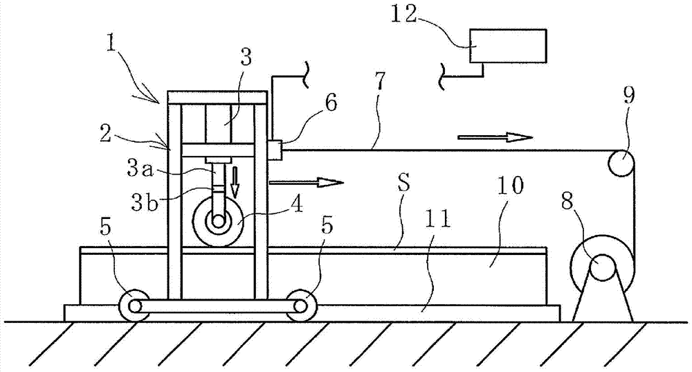
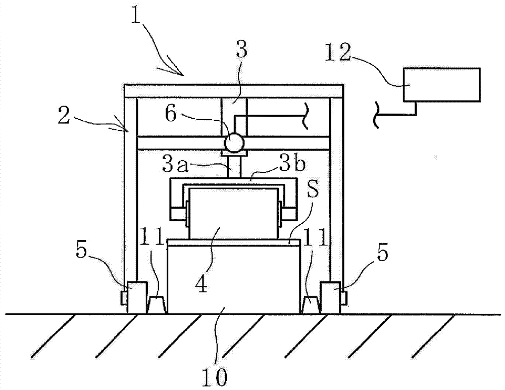
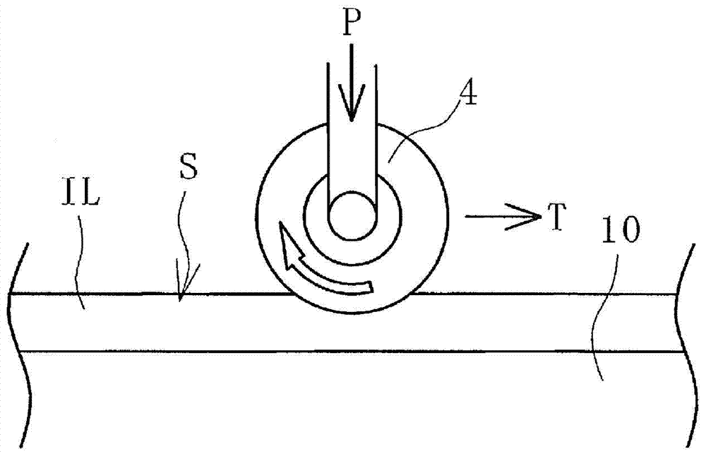
[0048] Use the structure with Figure 1 ~ Figure 3 Using the same measuring device as Measuring Device 1, the tensile force T (support roller passing resistance) was measured for the four evaluation objects (samples 1 to 4) listed in Table 1. The results are as follows Figure 7 shown. The size of each sample was 4000 mm in length, 150 mm in width, and 9 mm in thickness. The moving speed of the supporting roller is 0.92m / s, the outer diameter of the roller is 90mm, and the external force applied vertically downward to the supporting roller is 31N.

[0049] Table 1

[0050]

[0051] according to Figure 7 The results show that the passage resistance of energy-saving samples 2 and 4 is lower than that of general samples 1 and 3, respectively. This result shows that, including the relative magnitude of the passage resistance, the passage resistance can be measured with high accuracy, almost the same as when the support roller passage resistance i...


PUM


Abstract

An evaluation subject formed by a cut sample of a conveyor belt is mounted on a flat substrate with an inner periphery-side cover rubber layer located on the upper side, a support roller mounted in a frame is horizontally pulled and rolled in the longitudinal direction of the evaluation subject by pulling the frame by a wire while the support roller is pressed vertically downward against the upper surface of the evaluation subject at a preset pressure using a pneumatic cylinder without substantial deformation of the outer peripheral surface thereof, and tensile force in a horizontal direction measured at this time by a tensile force sensor connected to the wire is evaluated as resistance to moving over the support roller.

Description

technical field [0001] The present invention relates to a method and device for measuring the passing resistance of a supporting roller of a conveyor belt, more specifically, to a method for measuring the passing resistance of a supporting roller of a conveyor belt which can more easily and accurately measure the passing resistance of a supporting roller when the conveyor belt is running Method and device thereof. Background technique [0002] As we all know, the power consumption for driving the conveyor belt fluctuates depending on the type of the conveyor belt, peripheral equipment such as drive rollers, and changes in the weight of the load loaded on the conveyor belt. If the length of the conveyor belt equipment is longer, the number of supporting rollers supporting the conveyor belt increases, so the power consumption is mainly dominated by the power loss caused by the contact between the conveyor belt and the supporting rollers. Therefore, it is an important subject ...

Claims


Application Information

Patent Timeline
Patent Type & Authority Patents(China)
IPC IPC(8): G01N19/00
CPCG01N19/02G01N3/08
Inventor 天野成彦侯刚藤井透大洼和也
Owner THE YOKOHAMA RUBBER CO LTD
Why Eureka
Try Eureka