
Automobile electric telescopic pedal with double-station support function

An electric telescopic and double-station technology, which is applied to the arrangement of pedals or ladders, vehicle parts, transportation and packaging, etc., can solve the problems of short service life and easy damage of the motor, so as to improve the service life and avoid long-term stress , the effect of reasonable structural design

Active Publication Date: 2015-03-04
RUIAN NOBLE AUTO PARTS
View PDF5 Cites 49 Cited by
  • Summary
  • Abstract
  • Description
  • Claims
  • Application Information

AI Technical Summary

Problems solved by technology

[0004] (1) Under the position where the pedal is extended, the pedal is transmitted to the telescopic bracket due to its own gravity and the pressure on the human foot, and finally needs the driving force of the driving motor and the self-locking force to The force balance is obtained, therefore, the drive motor is often under pressure, the motor is easily damaged, and the service life is short;
[0005] (2) Under the pedal retraction position, the pedal is completely borne by the self-locking force of the motor due to its own weight, which causes the drive motor to bear the self-locking force for a long time when the pedal is not in use for a long time, which also causes the motor to easily damaged, short service life

Method used


Image

  • Automobile electric telescopic pedal with double-station support function
  • Automobile electric telescopic pedal with double-station support function
  • Automobile electric telescopic pedal with double-station support function

Examples


Embodiment Construction

[0022] The present invention is specifically described below by the embodiment, only for further illustrating the present invention, can not be interpreted as the limitation of protection scope of the present invention, the technical engineer of this field can make some non-essential improvements and improvements to the present invention according to the content of the above-mentioned invention Adjustment.

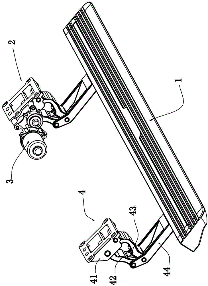
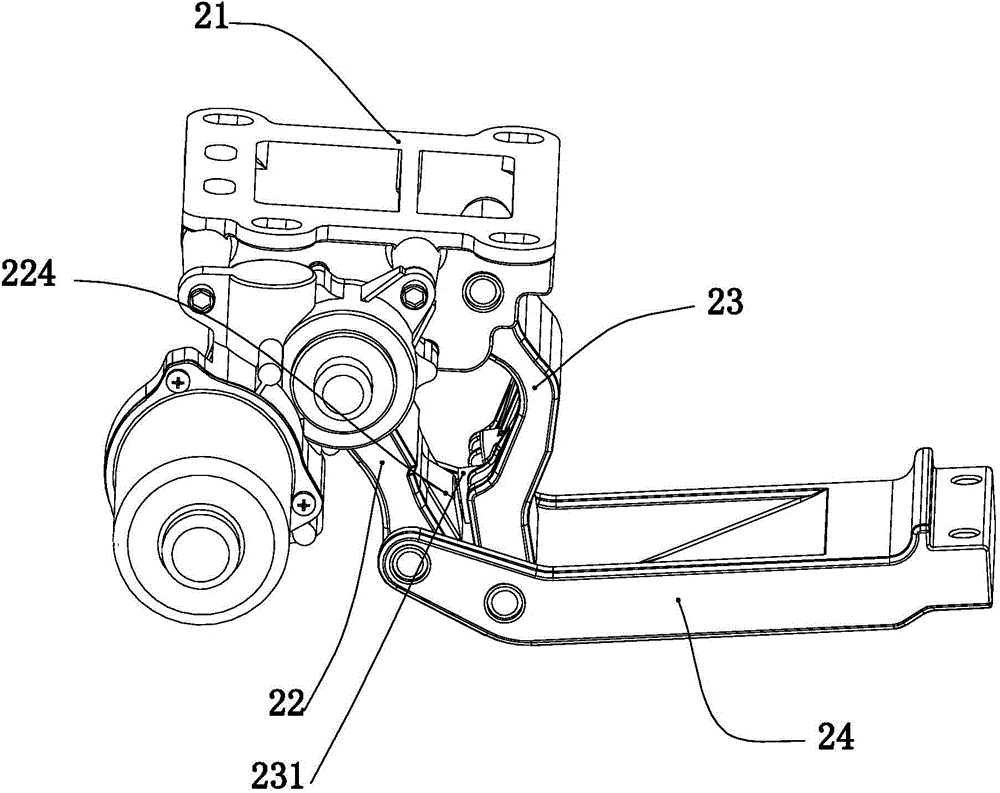
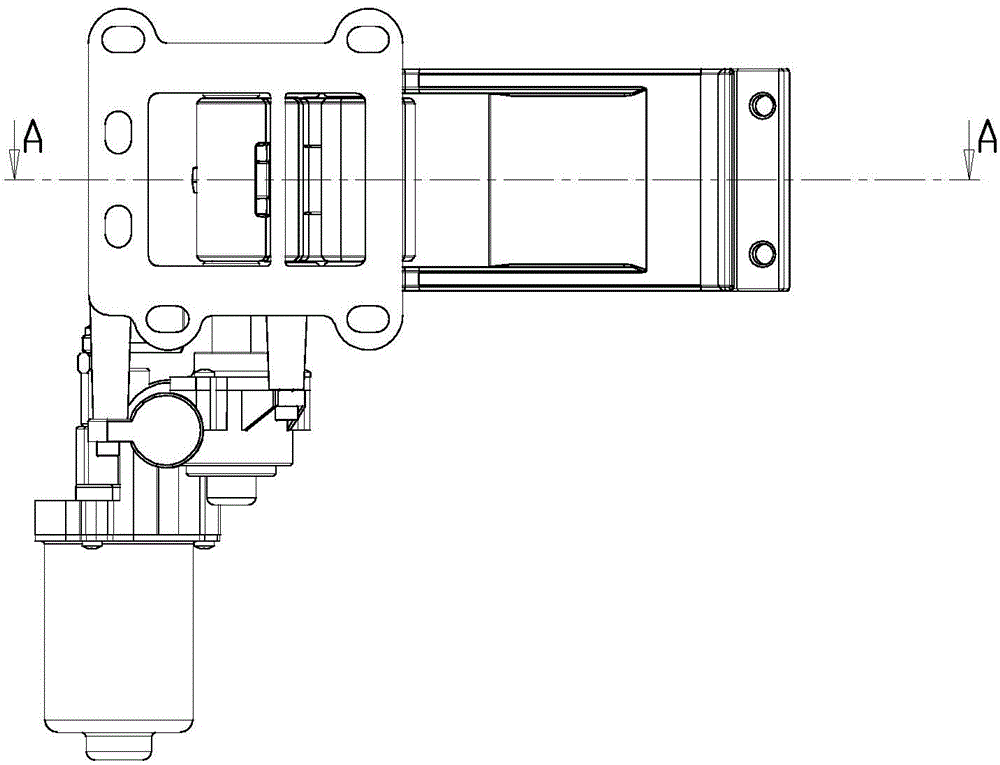
[0023] Such as Figure 1-7 The shown structural diagram of the specific embodiment of the present invention includes a pedal body 1, a first pedal mounting bracket assembly 2 and a forward and reverse motor 3, and the pedal first mounting bracket assembly 2 includes a first motor mounting bracket 21. The first main drive plate 22, the first slave linkage plate 23, and the first telescopic bracket 24. The side of the first motor mounting frame 21 is fixed with a forward and reverse motor 3. The first telescopic The outer end of the bracket 24 is fixedly supported and m...


PUM


Abstract

The invention discloses an automobile electric telescopic pedal with a double-station support function. The automobile electric telescopic pedal comprises a pedal body, a first pedal mounting bracket assembly and a positive and reverse rotation motor, wherein the first pedal mounting bracket assembly comprises a first motor mounting frame, a first main driving plate, a first auxiliary connecting plate and a first telescopic bracket, the outer end of the first telescopic bracket is fixedly connected with the pedal body in a support fit way, and the upper ends and the lower ends of the first main driving plate and the first auxiliary connecting plate are respectively hinged and fit with the inner ends of the first motor mounting frame and the first telescopic bracket to form a plane four-connecting rod structure; when the first telescopic bracket is controlled in the extending station state, a limiting convex block of the first main driving plate and a limiting convex block of the first auxiliary connecting plate are mutually abutted, jacked, limited and fit; when the first telescopic bracket is controlled in the retraction station state, the outer contour surface of the first main driving plate is provided with an outer convex part of the first main driving plate, and the outer convex part of the first main driving plate and the upper end surface of the first telescopic bracket are mutually limited and jacked. The automobile electric telescopic pedal has the advantages that the structure design is reasonable, the service life of the motor is prolonged, and the support stability of the pedal is guaranteed.

Description

technical field [0001] The invention relates to an automobile accessory, in particular to an electric telescoping pedal for automobiles with a double-station locking support function. Background technique [0002] Electric retractable pedals are installed on vehicles with high chassis such as off-road vehicles, and are used to provide pedal support devices for getting on and off the high-chassis vehicles. When pedal support is required, the pedals are stretched out. take back. [0003] Through retrieval, Chinese Patent Publication No. 203391872U discloses an electric pedal for automobiles. The structure of the electric pedal for automobiles includes a pedal body, two mounting brackets for fixing the pedal body, and a drive motor for driving the mounting bracket to perform telescopic movements. , the two mounting brackets are arranged on the same side of the pedal body, the two mounting brackets are provided with the telescopic bracket, the first connecting piece and the sec...

Claims


Application Information

Patent Timeline
Patent Type & Authority Applications(China)
IPC IPC(8): B60R3/02
CPCB60R3/02
Inventor 杜海武
Owner RUIAN NOBLE AUTO PARTS
Learn More