Novel train luggage rack

A technology for luggage racks and trains, applied in the field of luggage racks, can solve the problems of passengers not being able to observe luggage, passenger injuries, and insufficient light sources, etc., and achieve the effects of high practical value, labor-saving and convenient installation, and improved safety performance

Inactive Publication Date: 2015-03-04
JIANGSU ZHONGZHAN VEHICLE PARTS
View PDF0 Cites 1 Cited by
  • Summary
  • Abstract
  • Description
  • Claims
  • Application Information

AI Technical Summary

Problems solved by technology

After actual use, it is found that such a luggage rack has many deficiencies and potential safety hazards. First of all, because such a support surface is horizontal, the inertia of the train body when starting and braking and the vibration during high-speed driving can easily cause the luggage to fall from the luggage. The rack fell off, causing injury to passengers, and passengers could not observe their luggage. Secondly, the train sometimes runs at night, and some passengers need to read or do other things at this time, but the existing light sources in the train are insufficient. Passengers can't do these things very well, and the existing luggage racks can't meet people's actual needs

Method used


Image

  • Novel train luggage rack
  • Novel train luggage rack
  • Novel train luggage rack

Examples


Embodiment Construction

[0020] The present invention will be further described in detail below in conjunction with the accompanying drawings and specific embodiments.

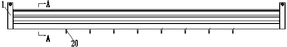
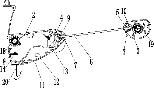
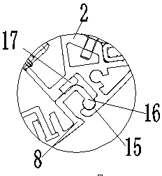
[0021] as attached Figure 1-6 The shown luggage rack of the present invention includes two skeletons 1, an upper cover 2, a tail cover 3, an upper pressure plate 4, a tail pressure plate 5, a tempered glass 6, a rubber 7 and a lower cover 8 which are placed relatively fixedly. ; The upper cover 2 and the tail cover 3 that are relatively inclined are arranged between the skeleton 1; the height of the vertical direction of the tail cover 3 is higher than the upper cover 2; the opposite sides of the upper cover 2 and the tail cover 3 are respectively An upper pressing plate 4 and a tail pressing plate 5 connected by threads are provided; the upper pressing plate 4 and the upper cover 2 form a first slot 9; the tail pressing plate 5 and the tail cover 3 form a second slot 10; the The first card slot 9 and the second card slot 10 are con...


PUM


Abstract

The invention relates to a novel train luggage rack. The novel train luggage rack comprises two frameworks which are oppositely and fixedly placed, an upper cover, a tail cover, an upper pressure plate, a tail pressure plate, tampered glass, rubber and a lower cover, wherein the upper cover and the tail cover which are oppositely arranged in an inclined manner are arranged between the frameworks; the tail cover in the vertical direction is higher than the upper cover; the upper pressure plate and the tail pressure plate which are in threaded connection with each other are respectively arranged at the positions, on the opposite sides, of the upper cover and the tail cover; the upper pressure plate and the upper cover form a first clamping groove; the tail pressure plate and the tail groove form a second clamping groove; the first clamping groove is connected with the second clamping groove through the tampered glass; the tampered glass is tightly connected with the first clamping groove and the second clamping through the rubber; the lower cover is connected with the lower part of the upper cover. According to the train luggage rack disclosed by the invention, the safety performance of a passenger is improved; meanwhile, the passenger can see the own luggage; an energy-saving lamp can be turned on by the passenger to meet a using requirement; the novel train luggage rack is simple in structure, convenient to mount and high in practicability, and is suitable for large-scale application.

Description

technical field [0001] The invention relates to a luggage rack, in particular to a luggage rack used on trains. Background technique [0002] Luggage rack is a kind of public facility for placing passengers' luggage. It is mostly used on public transportation such as railways. Existing luggage racks generally contain mounting brackets and support surfaces arranged on the mounting brackets. The mounting brackets Fixed on the outer wall of the compartment, the support surface is used to place luggage. After actual use, it is found that there are many deficiencies and potential safety hazards in such a luggage rack. First of all, because such a support surface is horizontal, the inertia of the train body when starting and braking and the vibration during high-speed driving can easily cause the luggage to fall from the luggage. The rack fell off, causing injury to passengers, and passengers could not observe their luggage. Secondly, the train sometimes runs at night. At this ti...

Claims


Application Information

Patent Timeline
IPC IPC(8): B61D37/00
CPCB61D37/003
Inventor 徐友胜
Owner JIANGSU ZHONGZHAN VEHICLE PARTS
Why Eureka
Try Eureka