High-pressure liquid protection ejector

A high-pressure liquid and injector technology, which is applied in the direction of liquid spray guns, weapon types, weapons without explosives, etc., can solve the problems of limited power, weak launch power, unsustainable supply and enhancement, etc., to achieve easy use and flexible disassembly Effect

Inactive Publication Date: 2015-03-04
HEZHOU UNIV +2
View PDF8 Cites 0 Cited by
  • Summary
  • Abstract
  • Description
  • Claims
  • Application Information

AI Technical Summary

Problems solved by technology

[0004] Aiming at the deficiencies of the prior art, the present invention provides a high-pressure liquid protective injector with the power of a high-pressure liquid protection injector, which can be continuously supplied and enhanced, and solves the problem of the existing warning Problems with the limited and weak power of the anti-riot jet self-defense device, and the launch power cannot be continuously supplied and enhanced

Method used


Image

  • High-pressure liquid protection ejector

Examples


Embodiment 1

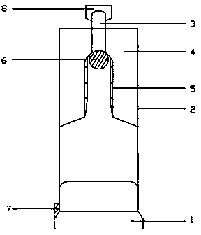
[0016] Embodiment 1: as figure 1 As shown, a high-pressure liquid protection injector includes a piston 1, a main body 2, an ejection port 3, a liquid storage chamber 4, and a one-way valve 5. It is characterized in that: the inside of the main body 2 has a cavity; the piston 1 Connect the cavity of the main body 2; the ejection port 3 is located at the front part of the cavity of the main body 2; One-way valve 5.

Embodiment 2

[0017] Embodiment 2: as figure 1 As shown, a high-pressure liquid protection injector includes a piston 1, a main body 2, an ejection port 3, a liquid storage chamber 4, a one-way valve 5, and an air pressure valve 6, and is characterized in that: the main body 2 has a cavity inside; The piston 1 is connected to the cavity of the main body 2; the ejection port 3 is located at the front of the cavity of the main body 2; There are one-way valves 5 at intervals between the cavities; the air pressure valve 6 is installed in the cavity of the main body 2 and connected to the discharge port 3; the piston 1 is equipped with an electric drive device and a power supply, and the electric drive device is started, and the piston 1 can quickly Moving back and forth in a straight line makes the gas in the umbrella handle main body 2 form high-pressure gas.

Embodiment 3

[0018] Embodiment 3: as figure 1 As shown, a high-pressure liquid protection injector includes a piston 1, a main body 2, an ejection port 3, a liquid storage chamber 4, a one-way valve 5, an air pressure valve 6, and a switch 7. It is characterized in that: the inside of the main body 2 has Cavity; the piston 1 is connected to the cavity of the main body 2; the ejection port 3 is located at the front of the cavity of the main body 2; the liquid storage chamber 4 is located around the front end of the cavity of the main body 2, and is filled with irritating liquid, and The cavity of the main body 2 is separated by a one-way valve 5; the air pressure valve 6 is installed in the cavity of the main body 2 and connected with the ejection port 3; the piston 1 is equipped with an electric drive device and a power supply, and the electric drive device is started, and the piston 1 1 can quickly move back and forth in a straight line, so that the gas in the umbrella handle main body 2 ...


PUM


Abstract

The invention relates to a police security apparatus and provides a high-pressure liquid protection ejector. The high-pressure liquid protection ejector comprises a piston 1, a main body 2, an ejection port 3, a liquid storage chamber 4 and a one-way valve 5. The high-pressure liquid protection ejector is characterized in that a cavity is formed in the main body 2; the piston 1 is connected with a cavity of the main body; the ejection port 3 is located in the front part of the cavity of the main body 2; the liquid storage chamber 4 is located around the front end of the cavity of the main body 2, and the liquid storage chamber 4 and the cavity of the main body 2 are spaced by the one-way valve 5. The high-pressure liquid protection ejector has the advantages that since high-pressure gas is produced as ejector power through pushing by a manual piston or an electric piston, the ejection power is not limited and can be continuously supplied and enhanced, and the problems that the power of the existing police antiriot ejection self-protection device is limited and is weak and the ejection power cannot be continuously enhanced are solved.

Description

technical field [0001] The invention relates to a high-pressure liquid protection injector. Background technique [0002] Existing anti-riot jet self-defense device is based on the limited propellant or high-pressure gas cylinder of its loading as the launch power, its power is limited and weak, and the launch power cannot be continuously supplied and strengthened. For example, the propellant of the anti-riot jet self-defense device forms a pressure in the injector tank, so that the stimulant can be sprayed out through the valve; the volume of the injector is small, and the filling amount of the propellant is relatively small, so the spray distance is also short. The spraying distance is only 3~6m. The existing knapsack anti-riot jet disperser uses high-pressure gas as the power source, and must be equipped with a high-pressure gas cylinder. If the high-pressure gas is used up, a new high-pressure gas cylinder must be replaced; there is also a heavy load, which is inconven...

Claims


Application Information

Patent Timeline
Patent Type & Authority Applications(China)
IPC IPC(8): F41B9/00
Inventor 毛献萍黄立丽陈建红蒋科化
Owner HEZHOU UNIV
Why Eureka
Try Eureka