Fabric Hydrostatic Pressure Tester

A hydrostatic pressure and tester technology, applied in instruments, measuring devices, scientific instruments, etc., can solve problems such as increasing the overall volume of the tester, limited adjustment range, and test result errors

Active Publication Date: 2017-03-29
WENZHOU DARONG TEXTILE INSTR
View PDF7 Cites 0 Cited by
  • Summary
  • Abstract
  • Description
  • Claims
  • Application Information

AI Technical Summary

Problems solved by technology

[0003] The traditional hydrostatic pressure tester for fabrics includes a fabric installation platform, which is located above the fabric and is provided with a pressing block for fixing the fabric to the installation platform, and is located below the fabric and is provided with a detection pipeline connected with a water supply tank, and a piston is provided in the water supply tank Plate and the piston rod to adjust the position of the piston plate. The piston squeezes the water in the water supply tank to the detection pipe to gradually increase the water pressure on the fabric to achieve the function of testing the hydrostatic pressure. The water pressure gauge is often set in the detection pipe. Detect the water pressure in the pipeline. However, since the end surface of the piston plate facing the water has a certain area, the minimum displacement of the piston rod is limited by the limit of its driving end, so the minimum amount of adjusted water pressure is limited, resulting in certain errors in the test results. Secondly, the piston rod has a certain length. When the piston rod returns to its original position and most of it exits the water supply tank, it takes up a part of the volume outside the water supply tank, which invisibly increases the overall volume of the tester. The adjustment range of the piston plate adjusted by the piston rod should not be too large, so that the adjustment range is limited

Method used


Image

  • Fabric Hydrostatic Pressure Tester
  • Fabric Hydrostatic Pressure Tester
  • Fabric Hydrostatic Pressure Tester

Examples


Embodiment Construction

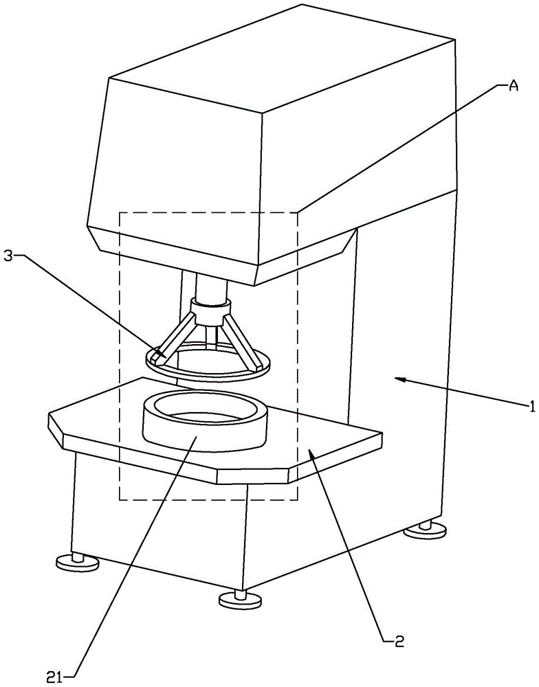
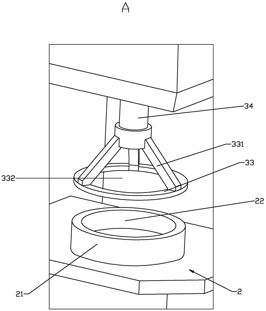
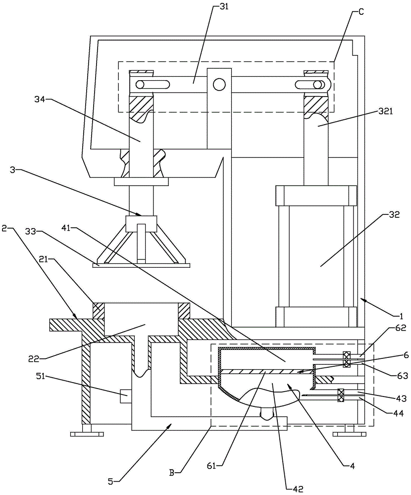
[0023] like figure 1 — Figure 5 As shown, the present invention discloses a fabric hydrostatic pressure tester, comprising a frame 1, a fabric mounting table 2 arranged on the frame 1, a fabric fixing mechanism 3, a water supply tank 4, a detection pipeline 5, and a fabric fixing mechanism 3 is located above the table top of the fabric installation platform 2, and the detection pipeline 5 is located below the table surface of the fabric installation platform 2 and communicates with the water supply tank 4. Squeeze or extract the water adjusting pressure mechanism 6, the water adjusting pressure mechanism 6 includes a piston plate 61 that slides in the water supply tank 4, and the piston plate 61 separates the space in the water supply tank 4 into an adjustment chamber 41 and a detection pipe 5 Unicom's water supply chamber 42, water regulating mechanism 6 also comprises the air inlet pipe 62 that regulates chamber 41 and gas source Unicom and the air outlet pipe 63 that comm...


PUM


Abstract

The invention relates to a tester for hydrostatic pressure of a fabric. The tester comprises a rack, and a fabric mounting table, a fabric fixing mechanism, a water supply tank and a detection pipeline which are arranged on the rack, wherein the fabric fixing mechanism is positioned above the table-board of the fabric mounting table; the detection pipeline is positioned below the table-board of the fabric mounting table and is communicated with the water supply tank; a water manometer is arranged in the detection pipeline; a water pressure adjusting mechanism through which the water is extruded or pumped to the detection pipeline is arranged in the water supply tank; the water pressure adjusting mechanism comprises a piston plate which slides on the water supply tank; the space in the water supply tank is separated into an adjusting cavity and a water supply cavity communicated with the detection pipeline by virtue of the piston plate; the water pressure adjusting mechanism also comprises an air inlet pipeline through which the adjusting cavity is communicated with an air source, and an air outlet pipeline communicated with the outside; and control valves for regulating the on / off state are respectively arranged on the air inlet pipeline and the air outlet pipeline. With the adoption of the technical scheme, the tester for the hydrostatic pressure of the fabric provided by the invention is wide in test range, small in equipment size and accurate in detection.

Description

technical field [0001] The invention relates to a device for testing the hydrostatic pressure performance of fabrics, in particular to a fabric hydrostatic pressure tester. Background technique [0002] Fabric is a flat and soft piece formed by crossing, knotting or bonding small and long objects. As the main material of clothing, its various use indicators are also highly valued by the clothing industry. Among them, the hydrostatic pressure performance of the fabric is an indicator of the strength of the waterproof performance of the waterproof clothing, that is, the hydraulic pressure value required for water or non-corrosive liquid to start seeping from the surface of the fabric. [0003] The traditional hydrostatic pressure tester for fabrics includes a fabric installation platform, which is located above the fabric and is provided with a pressing block for fixing the fabric to the installation platform, and is located below the fabric and is provided with a detection pi...

Claims


Application Information

Patent Timeline
Patent Type & Authority Patents(China)
IPC IPC(8): G01N13/04
Inventor 陈建勇夏祝孟张孟胜陈绍达周继业杨雪松
Owner WENZHOU DARONG TEXTILE INSTR
Why Eureka
Try Eureka