
Backlight module lighting fixture

A lighting fixture and backlight module technology, which is applied in optics, nonlinear optics, instruments, etc., can solve the problems of low lighting detection efficiency and low accuracy, so as to improve the one-time lighting success rate, shorten the adjustment cycle, The effect of high degree of automation

Inactive Publication Date: 2017-02-15
施杰
View PDF5 Cites 0 Cited by
  • Summary
  • Abstract
  • Description
  • Claims
  • Application Information

AI Technical Summary

Problems solved by technology

[0003] The purpose of the present invention is to design a backlight module lighting fixture for the problems of low efficiency and low accuracy of the existing backlight module lighting detection

Method used


Image

  • Backlight module lighting fixture
  • Backlight module lighting fixture
  • Backlight module lighting fixture

Examples


Embodiment Construction

[0020] The present invention will be further described below in conjunction with the accompanying drawings and embodiments.

[0021] Such as Figure 2-7 shown.

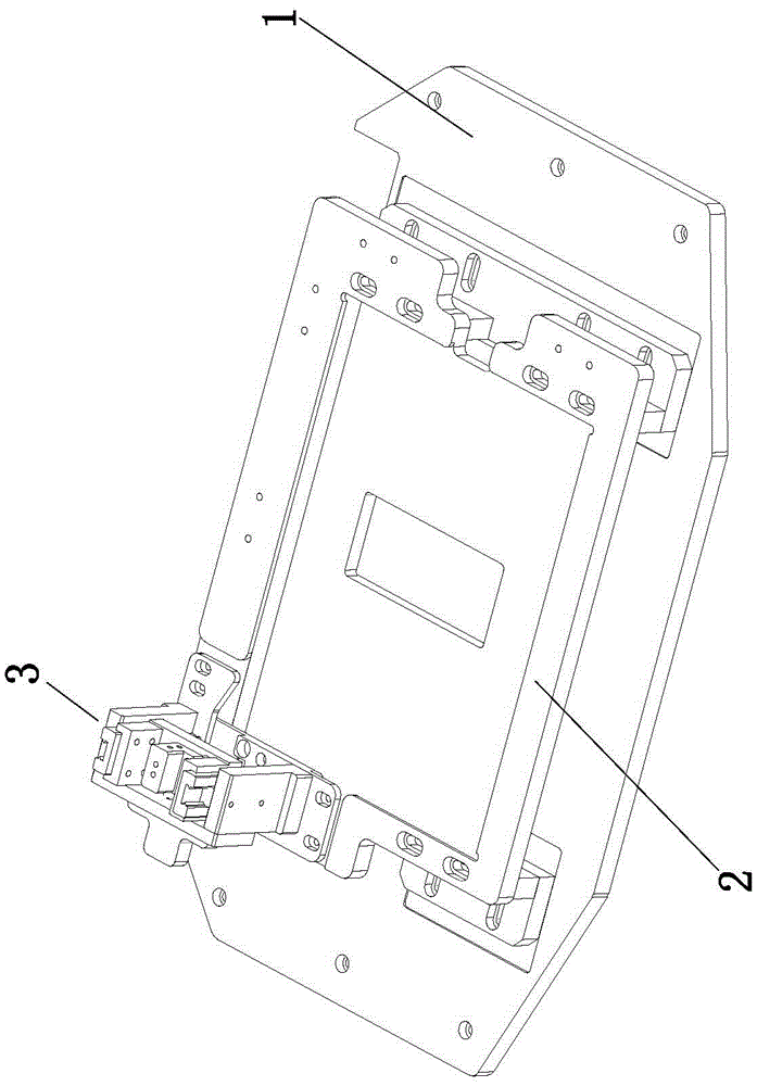
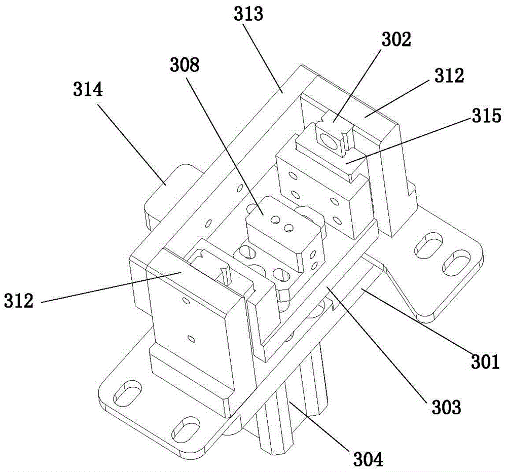
[0022] A backlight module lighting fixture, which includes a base plate 1, a product fixture 2 and a lighting head part 3, the product fixture 2 is installed on the bottom plate 1, and the lighting head part 3 is installed on the product fixture 2 and The relative position of gold finger 4 of the product, such as figure 2 As shown, the lighting pressure head part 3 is as image 3 , 4 As shown, it includes a base 301, which is symmetrically installed on the guide rail 302 on the base 301, and the two sides of the U-shaped indenter 303 are installed on the guide rail 302 and can move up and down under the drive of the cylinder 304, and are connected at the bottom of the U-shaped indenter 303. There is an inclined push block 305 (such as Figure 6 ), in the groove on the base 301 is installed a sliding block 306 fo...


PUM


Abstract

The invention relates to a backlight module lighting fixture. The backlight module lighting fixture comprises a soleplate (1), a product fixture (2) and a lighting pressure head part (3), wherein the product fixture is installed on the soleplate, the lighting pressure head part is installed on the product fixture, and the backlight module lighting fixture is characterized in that the lighting pressure head part (3) comprises a base (301), wherein the base (301) is symmetrically installed on a guide rail (302), two sides of a U-shaped pressure head (303) are installed on the guide rail (302) and can move up and down, the bottom of the U-shaped pressure head (303) is connected with an oblique surface push block (305), a slide block (306) is installed in a groove on the base (301), the oblique surface push block (305) moves downwards to push the slide block (306) to move towards a gold finger so as to enable the gold finger to be aligned; a lighting electrode (307) is installed on an electrode base (308); a lower magnetic block (310) is installed on the base (301), and an upper magnet (311) is installed on the lower bottom surface of the U-shaped pressure head (303). By adopting the backlight module lighting fixture, the one-time lighting success rate can be increased, and the one-time lighting success rate can reach more than 99 percent.

Description

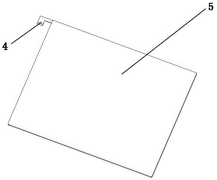
technical field [0001] The invention relates to an electrical inspection tool, in particular to an electrical inspection tool used in the manufacturing process of a liquid crystal display, in particular to a lighting fixture for a backlight module. Background technique [0002] At present, in the production process of liquid crystal display, it is necessary to figure 1 The inspection of the BLU products shown is mainly to inspect the power-on status of the LED on the BLU, that is, to detect the lighting rate. The existing detection method is to manually align the electrode with the gold finger 4 on the product 5, and rely on the experience of the inspector and hand pressure to light up at least 18 lamps. This method is not only labor-intensive, but also because the gold finger is easily deformed. Do not use excessive force on the damage, otherwise the golden finger will be damaged. Therefore, the operation requirements are very high, and multiple inspections are required to...

Claims


Application Information

Patent Timeline
Patent Type & Authority Patents(China)
IPC IPC(8): G02F1/13
CPCG02F1/1303G02F1/1309
Inventor 施杰
Owner 施杰
Learn More