
Automatic feeding device for terminal crimping machine

A terminal crimping machine and automatic feeding technology, which is applied in the direction of connection, circuit/current collector parts, electrical components, etc. Slow material speed and other problems, to reduce material jams or blanking errors, improve automatic feeding efficiency, and stable blanking

Active Publication Date: 2017-06-06
GUANGDONG ZHONGDE CABLE +1
View PDF6 Cites 0 Cited by
  • Summary
  • Abstract
  • Description
  • Claims
  • Application Information

AI Technical Summary

Problems solved by technology

[0002] In the cable manufacturing industry, with the development of terminal automatic crimping machines, the terminal feeding device is also constantly improving. Since the terminals are generally small in size, it is not easy to pick and place manually. Therefore, in order to improve production efficiency and avoid potential safety hazards, it is necessary to use The traditional manual feeding method is changed to a mechanized automatic feeding device, but the existing automatic feeding device has the following defects: (1) The reserve of the feeding device is small, resulting in frequent feeding; (2) The feeding device The unloading of the feeder is unstable, and it is easy to cause the phenomenon of material jamming or feeding reverse; (3) The feeding speed of the feeding device is slow, which affects the production efficiency of the crimping machine; (4) The structure is complex, not easy to process and manufacture, and the cost is high

Method used


Image

  • Automatic feeding device for terminal crimping machine
  • Automatic feeding device for terminal crimping machine
  • Automatic feeding device for terminal crimping machine

Examples


Embodiment Construction

[0031] The present invention is further described in conjunction with the following examples.

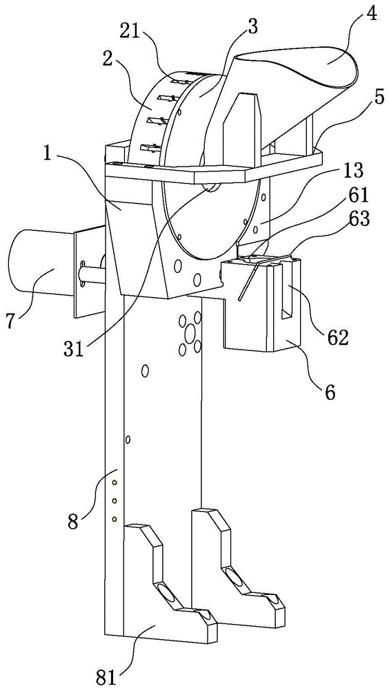
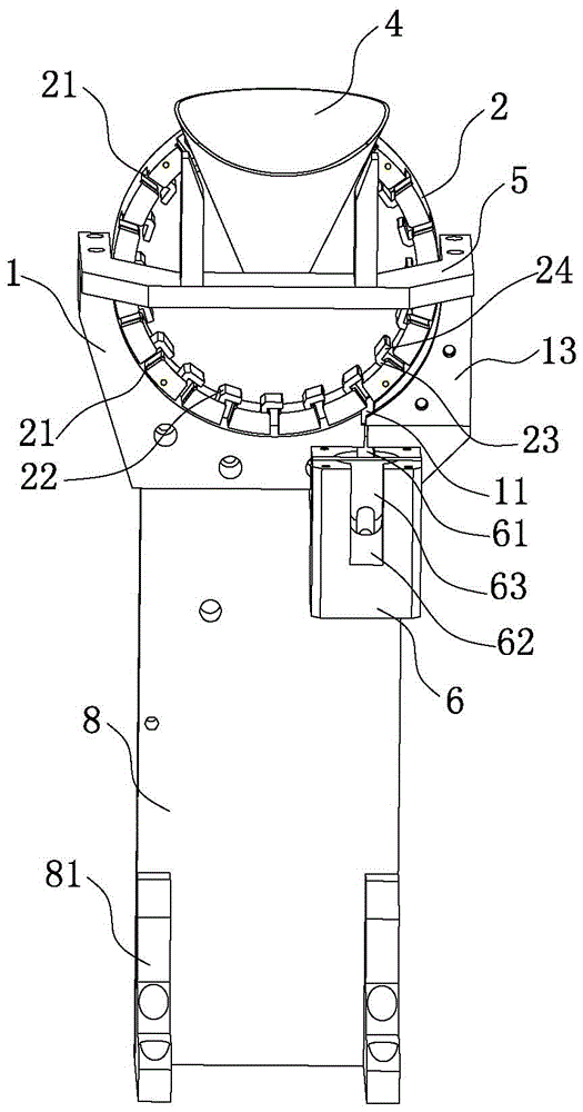
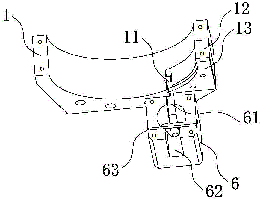
[0032] The specific implementation of the automatic feeding device of a terminal crimping machine created by the present invention is as follows: figure 1 and figure 2 As shown, it includes a base 1, a turntable 2 with a cavity, a driving mechanism for driving the turntable 2 to rotate, and a material guide 6 for introducing materials into the workbench of the crimping machine. The circumferential surface is evenly provided with several blanking holes 21, the base 1 is provided with a blanking hole 11 communicating with the blanking hole 21, the material guide 6 is also fixed on the base 1, the material guide 6 is provided with a material guide groove 61, and the material guide 6 is provided with a material guide groove 61 for falling The material hole 11 communicates with the material guide groove 61 .

[0033] The upper cover of the turntable 2 is provided with a cover plate 3 ...


PUM


Abstract

The invention relates to an automatic material-loading device of a terminal crimping machine. The automatic material-loading device comprises a pedestal, a rotating plate, a drive mechanism and a material guiding element. The rotating plate is arranged at the pedestal in a rotating mode; a plurality of laying-off holes are uniformly formed at the circumference surface of the rotating plate; a blanking hole communicated with the laying-off holes is formed in the pedestal. The material guiding element is provided with a material guiding slot communicated with the blanking hole. A material blocking plate is arranged at one side, facing the rotating direction of the rotating plate, of each laying-off hole inside the rotating plate and is used for preventing materials from falling off from the laying-off hole loaded with the materials to the inside the rotating plate during the rotating process, thereby improving the automatic feeding efficiency. A cover plate covers the rotating plate and a feeding inlet is formed in the cover plate; and a feeding hopper is arranged at the feeding inlet. With the rotating plate and the feeding hopper, the material storage capability of the automatic material-loading device can be substantially improved; and the number of times for material loading can be reduced. The provided automatic material-loading device has advantages of simple structure, convenient processing and manufacturing, low cost, and stable material laying off; and a material clamping phenomenon or wrong laying-off phenomenon can be reduced.

Description

technical field [0001] The invention relates to the technical field of feeding devices for crimping machines, in particular to an automatic feeding device for terminal crimping machines applied to cables. Background technique [0002] In the cable manufacturing industry, with the development of terminal automatic crimping machines, the terminal feeding device is also constantly improving. Since the terminals are generally small in size, it is not easy to pick and place manually. Therefore, in order to improve production efficiency and avoid potential safety hazards, it is necessary to use The traditional manual feeding method is changed to a mechanized automatic feeding device, but the existing automatic feeding device has the following defects: (1) The reserve of the feeding device is small, resulting in frequent feeding; (2) The feeding device The unloading of the feeder is unstable, and it is easy to cause the phenomenon of material jamming or feeding reverse; (3) The fee...

Claims


Application Information

Patent Timeline
Patent Type & Authority Patents(China)
IPC IPC(8): H01R43/055
CPCH01R43/055
Inventor 刘发义谭春红
Owner GUANGDONG ZHONGDE CABLE
Learn More