Laminar-flow centrifugal separator

A technology of centrifugal separator and separation structure, which can be used in centrifuges, centrifuges with rotating drums, etc., and can solve the problem that the separation of components is not very efficient.

Inactive Publication Date: 2015-03-04
COMMISSARIAT A LENERGIE ATOMIQUE ET AUX ENERGIES ALTERNATIVES +1
View PDF13 Cites 0 Cited by
  • Summary
  • Abstract
  • Description
  • Claims
  • Application Information

AI Technical Summary

Problems solved by technology

Again, the separation of components is not very efficient

Method used


Image

  • Laminar-flow centrifugal separator
  • Laminar-flow centrifugal separator
  • Laminar-flow centrifugal separator

Examples


Embodiment Construction

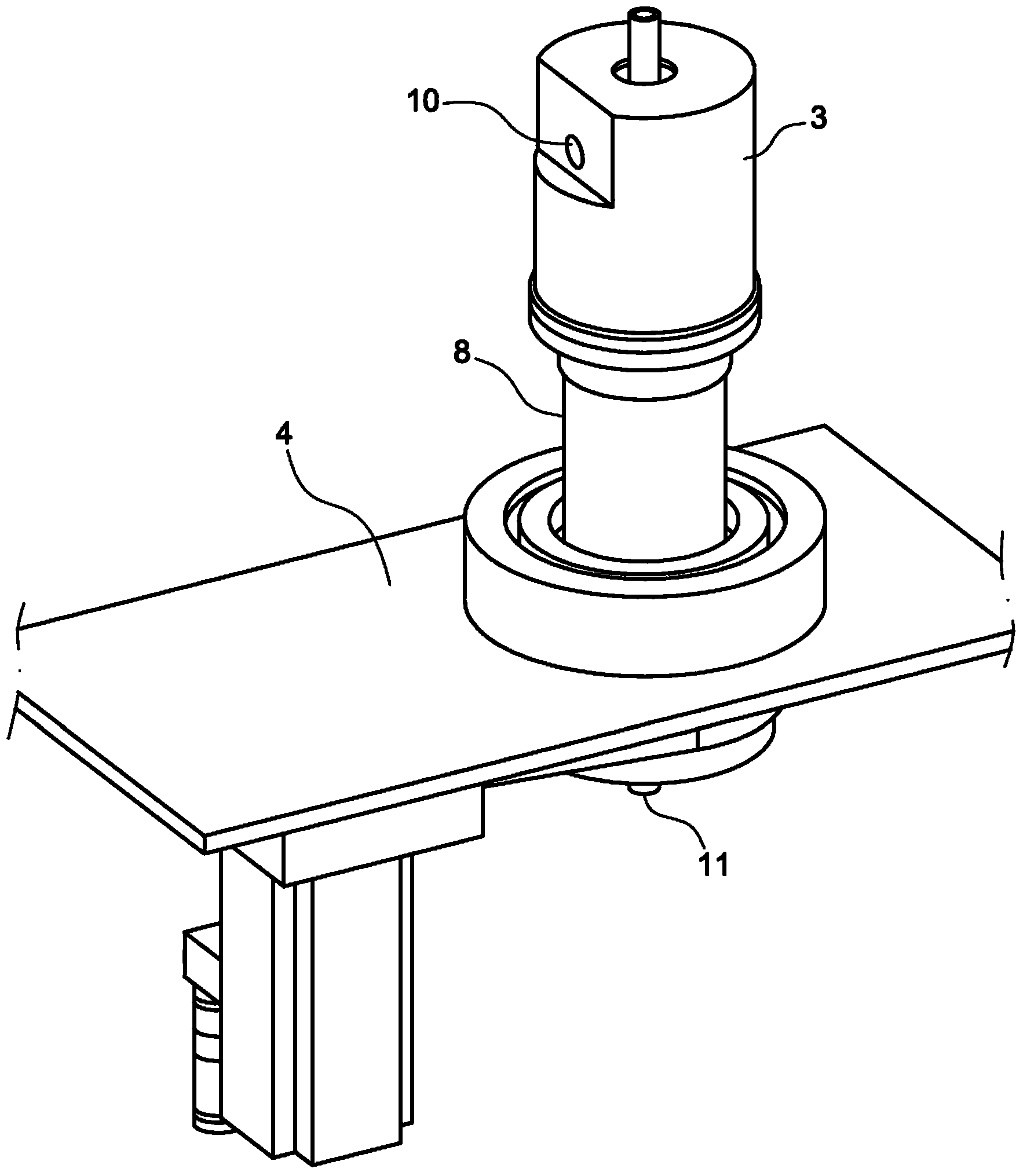
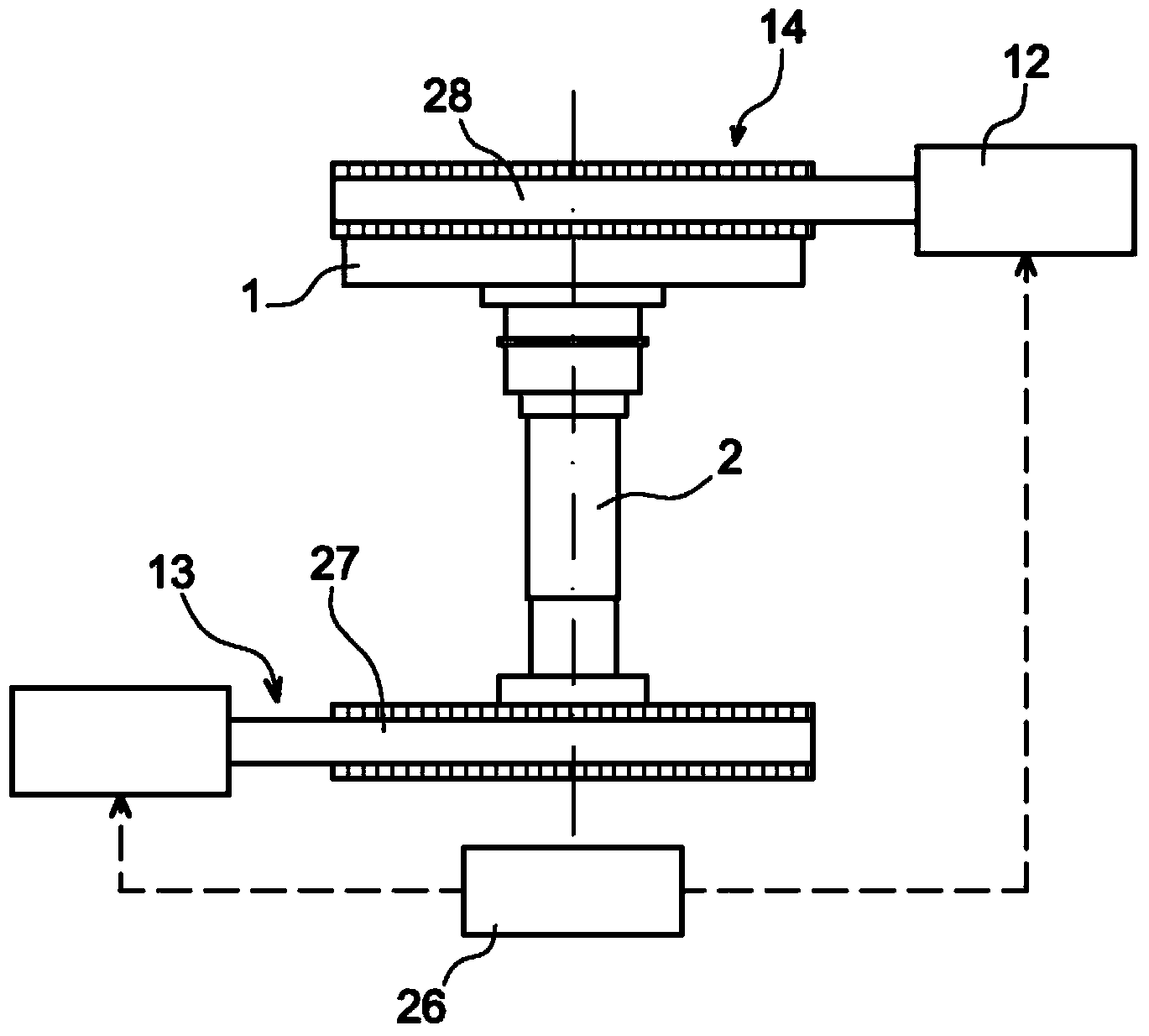
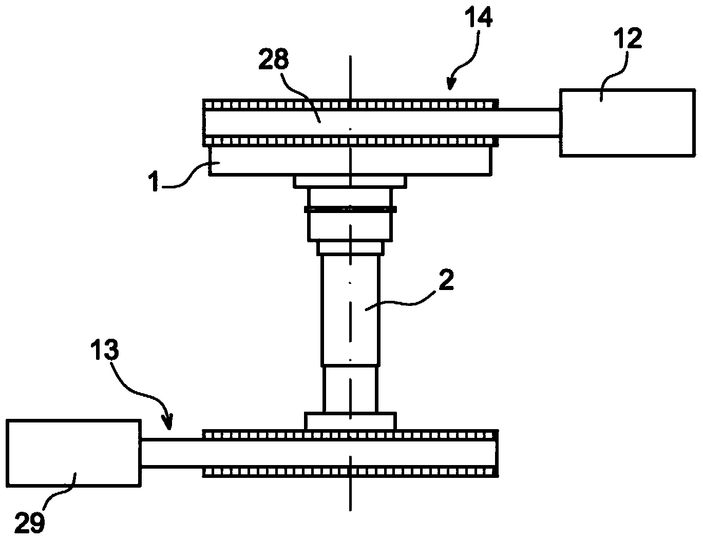
[0019] The separator comprises a rotating drum 1 constituted by a cylindrical body forming a side wall 8 and a central shaft 2 . The central shaft 2 and the rotating drum 1 are maintained between the upper stationary head 3 and the lower frame 4 with a constant distance maintained between the upper stationary head 3 and the lower frame 4 . The mixture is introduced via a duct 5 contained in the central shaft 2, in this case from the top and from the stationary head 3 and reaches the rotating drum 1 via an opening 6 which may be located at the bottom of the duct 5 or along the duct 5 height distribution. The central shaft 2 supports a conical structure made up of separate sectors 7 which, in contrast to the flower shape, overlap the entire height of the barrel to the liquid recovery manifold 20 or part of said height and rotate towards The side walls 8 of the drum 1 are inclined downwards. The segments 7 are angularly offset from one segment to the other such that their gap 9...


PUM


Abstract

The invention relates to a centrifugal separator, the rotating bowl (1) of which is provided with tapered structures divided into sectors (7) separated by angularly offset gaps (9) so as to promote a uniform and spiral flow of fluid therein, said flow being laminar and greatly enhancing the efficiency of the separation. In the case of two-phase or three-phase suspensions, a cake is obtained on the side wall (8). A scraper (15) rotating at a slightly different speed can be added so as to simultaneously enable said solid cake to be directed toward the outlet and continuous operation.

Description

technical field [0001] The invention relates to a laminar flow centrifugal separator. Background technique [0002] Separators have been designed for the separation of fluid mixtures containing solids, liquids or gases in various proportions into at least one liquid component and one solid-containing component, especially in suspension in the liquid phase A mixture of liquids and solids. An attempt is then made to separate the constituents of the mixture well and to obtain solid components in compact form or agglomerates with less residual suspension constituents. Even when the formation of lumps causes a high flow resistance or a large sectional reduction (sectional reduction), it is usually attempted to extract the solid components by means of separators and, if possible, with the solid components in the rotating drum Formation takes place in a continuous manner for extraction (despite its compact nature) without accumulation of the aforementioned solid components in the...

Claims


Application Information

Patent Timeline
Patent Type & Authority Applications(China)
IPC IPC(8): B04B1/08B04B7/14
CPCB04B11/02B04B1/08B04B7/14B04B11/08
Inventor 戴维·彻让德让-皮埃尔·菲劳德乔尔·罗宾图尤尼瑞尼亚·兰德瑞曼安特纳
Owner COMMISSARIAT A LENERGIE ATOMIQUE ET AUX ENERGIES ALTERNATIVES
Why Eureka
Try Eureka