Disc punching clamp

A technology for punching fixtures and discs, applied in the field of tooling fixtures, can solve the problems of difficult clamping and positioning, production efficiency, low qualified rate of workpiece products, and reduced production efficiency, so as to achieve accurate punching, improve quality and work efficiency. Efficient, quick pick and place

Inactive Publication Date: 2015-03-11
SUZHOU FUMAI PRECISION MACHINERY
View PDF5 Cites 28 Cited by
  • Summary
  • Abstract
  • Description
  • Claims
  • Application Information

AI Technical Summary

Problems solved by technology

[0002] In the process of modern industrial production, fixtures have been widely used in the process of drilling workpieces. When drilling discs, because the disc body is round, it is not easy to clamp and position, and the accur

Method used


Image

  • Disc punching clamp
  • Disc punching clamp
  • Disc punching clamp

Examples


Embodiment Construction

[0015] The present invention is described below in conjunction with accompanying drawing.

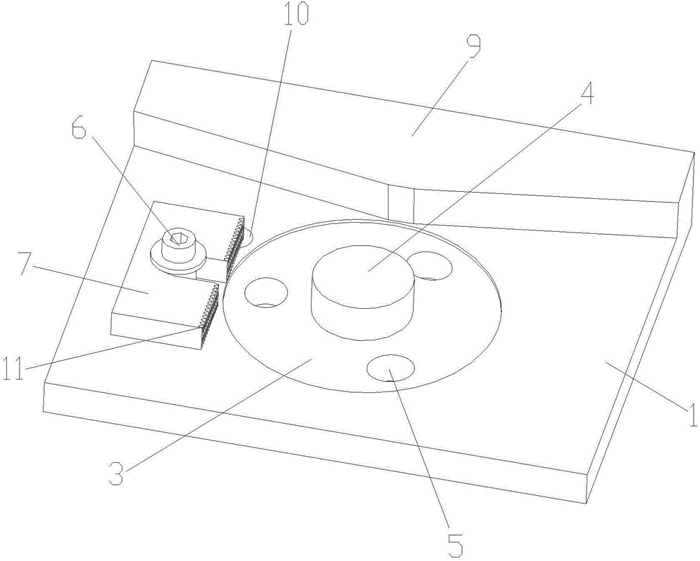
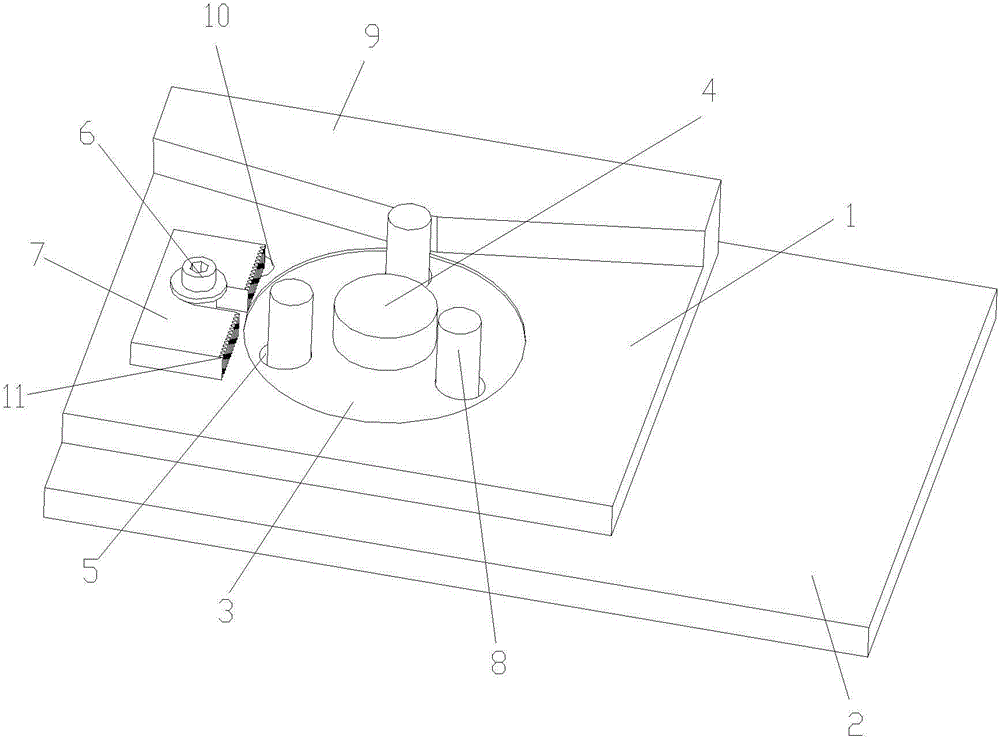
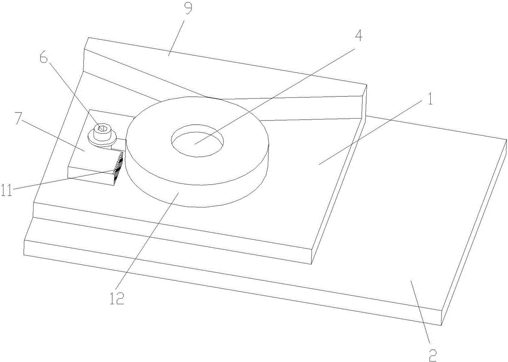
[0016] as attached Figure 1-3 Shown is a disc punching jig according to the present invention, including a base 1 and a push rod seat 2; the base 1 is provided with a disc groove 3; the center of the disc groove 3 is provided with a positioning column 4. There are three ejector pin holes 5 evenly distributed in the disk groove 3 and distributed at 120°; one side of the disk groove 3 is provided with a block 7 connected by a bolt 6 and with the bolt 6 as the rotation center , the block 7 is provided with a locking tooth 11 on the end face of the disc groove 3 side; the side of the base 1 is provided with a baffle plate 9; The matched push rod 8; a bolt hole 10 is provided on the outer side of the disc groove 3 for adjusting the position of the block 7.

[0017] Such as figure 2 As shown, when in use, the disc 12 to be processed is placed on the positioning column 4, one side of the ...


PUM


Abstract

The invention discloses a disc punching clamp which comprises a base and a jacking rod base, wherein a disc slot is arranged in the base; a positioning pillar is arranged at the center of the disc slot; jacking rod holes are uniformly distributed in the disc slot; a clamping block is arranged on one side of the disc slot; the clamping block is connected through a bolt and takes the bolt as a rotating center; a baffle is arranged at one end of the base; jacking rods matched with the jacking rod holes in the disc slot are arranged on the jacking rod base. According to the disc punching clamp, the positioning pillar is arranged at the center of the disc slot, the clamping block which is connected through the bolt and takes the bolt as the rotating center is arranged on one side of the disc slot, a to-be-processed disc slot is fixedly arranged on the positioning pillar, the clamping block is rotated and adjusted and is clamped on a disc, the baffle on one side is resisted against the disc, the disc is fixed and then is punched, and the jacking rod base is inserted into the jacking rod holes so as to push out the disc after being punched, so that the accurate punching for the disc is realized, the quick fetching of the disc is realized and the product quality and the working efficiency are increased.

Description

technical field [0001] The invention relates to a disc punching jig, which belongs to the technical field of tooling jigs. Background technique [0002] In the process of modern industrial production, fixtures have been widely used in the process of drilling workpieces. When drilling discs, because the disc body is round, it is not easy to clamp and position, and the accuracy and precision of drilling cannot be achieved. A good guarantee leads to low production efficiency and low pass rate of workpiece products, which greatly reduces production efficiency and is not conducive to production. Contents of the invention [0003] In view of the above-mentioned technical problems, the object of the present invention is to propose a disc punching jig that is stable and accurate. [0004] The technical solution of the present invention is achieved in the following way: a disc punching jig includes a base and a push rod seat; the base is provided with a disc groove; the center of ...

Claims


Application Information

Patent Timeline
IPC IPC(8): B23Q3/06
CPCB23Q3/00B23Q2703/10
Inventor 顾卫建
Owner SUZHOU FUMAI PRECISION MACHINERY
Why Eureka
Try Eureka