Two-speed hydraulic cylinder and lifting mechanism applying same

A hydraulic cylinder and speed technology, which is applied in the direction of lifting frame, lifting device, fluid pressure actuating device, etc., can solve the problems of complex lifting mechanism, large space, occupation, etc., and achieve the effect of protecting safety, improving service life and reducing impact

Active Publication Date: 2015-03-11
江苏海力达机电制造有限公司
View PDF5 Cites 1 Cited by
  • Summary
  • Abstract
  • Description
  • Claims
  • Application Information

AI Technical Summary

Problems solved by technology

[0003] However, adding additional external throttling switching equipment will make the hydraulic system and m

Method used


Image

  • Two-speed hydraulic cylinder and lifting mechanism applying same
  • Two-speed hydraulic cylinder and lifting mechanism applying same
  • Two-speed hydraulic cylinder and lifting mechanism applying same

Examples


Embodiment Construction

[0023] The specific implementation manners of the present invention will be further described in detail below in conjunction with the accompanying drawings and embodiments.

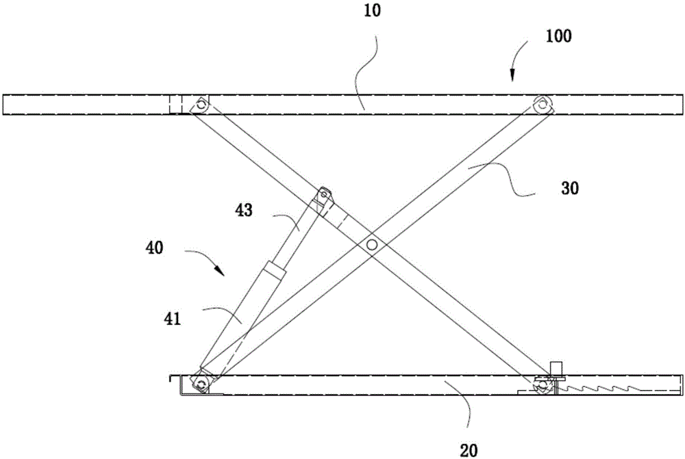
[0024] see figure 1 , the embodiment of the present invention provides a lifting mechanism 100, comprising a bearing platform 10, a base 20 arranged relative to the bearing platform 10, a connecting rod structure 30 connecting the bearing platform 10 and the base 20, and two ends respectively connected to the base 20 and the connecting rod structure 30 Articulated two-stage speed hydraulic cylinder 40. The carrying platform 10 is used for carrying objects to be lifted, such as vehicles. The connecting rod structure 30 is roughly in the shape of an "X". The ability to lift. It can be understood that, as long as the supporting platform 10 has the ability to lift relative to the base 20 , the connecting rod structure 30 can also be other structures such as a parallelogram. The two-stage speed hydraulic c...


PUM


Abstract

The invention provides a two-speed hydraulic cylinder and a lifting mechanism applying the same. The invention relates to the two-speed hydraulic cylinder and the lifting mechanism, wherein the hydraulic cylinder comprises a cylinder body and a piston movably arranged in the cylinder body; an oil channel, a fast hole and a damping hole are arranged at the bottom of the cylinder body; the oil channel is used for being communicated with an external oil way; the cylinder body comprises a motion chamber for allowing the piston to do piston motion; the two ends of the fast hole and the two ends of the damping hole are communicated with the oil channel and the motion chamber respectively; the end of the fast hole, which has a large diameter, is communicated with the motion chamber; the hydraulic cylinder further comprises a limit valve rod and an elastic piece, and the limit valve rod is opposite to the fast hole; the end, accommodated in the motion chamber, of the limit valve rod is provided with a blind hole; the elastic piece and part of the limit valve rod are accommodated in the blind hole; and the other part of the limit valve rod extends out of the blind hole under the elastic action of the elastic piece. During the oil return process of the hydraulic cylinder, when the limit valve rod is not propped against the fast hole, the hydraulic cylinder returns oil simultaneously through a fast channel and a slow channel, and when the limit valve rod is propped against and seal the fast hole, the hydraulic cylinder returns oil only through the slow channel.

Description

technical field [0001] The invention relates to a two-stage speed hydraulic cylinder, in particular to a two-stage speed hydraulic cylinder applied to a lifting mechanism. Background technique [0002] Lifting mechanisms (such as vehicle cranes) generally include hydraulic cylinders for providing lifting power to the lifting mechanism. Currently commonly used hydraulic cylinders generally have a constant running speed of the piston rod during the process of working and resetting, that is, the piston rod only has the ability to run at a single speed. Therefore, when the lifting mechanism needs to descend rapidly in the first half and descend slowly in the second half, it can only be realized with the help of an additional external throttling switching device. [0003] However, adding an additional external throttling switching device will make the hydraulic system and mechanical system of the lifting mechanism more complicated and require a larger space. Contents of the in...

Claims


Application Information

Patent Timeline
IPC IPC(8): F15B15/14B66F7/08
CPCF15B15/1428F15B15/149F15B15/224
Inventor 傅勇刚左超
Owner 江苏海力达机电制造有限公司
Why Eureka
Try Eureka