

Mounting structure for appliance guide rail
A technology for installation structure and electrical appliances, which is applied to circuits, electrical switches, electrical components, etc., can solve the problems of guide rails shaking, high production and processing costs, increased costs, etc., and achieve stable installation of circlips, guide rails, and production costs. Effect
- Summary
- Abstract
- Description
- Claims
- Application Information
AI Technical Summary
Problems solved by technology
Method used
Image

Examples
Embodiment Construction
[0040] The present invention will be described in detail below in conjunction with the accompanying drawings and specific embodiments.
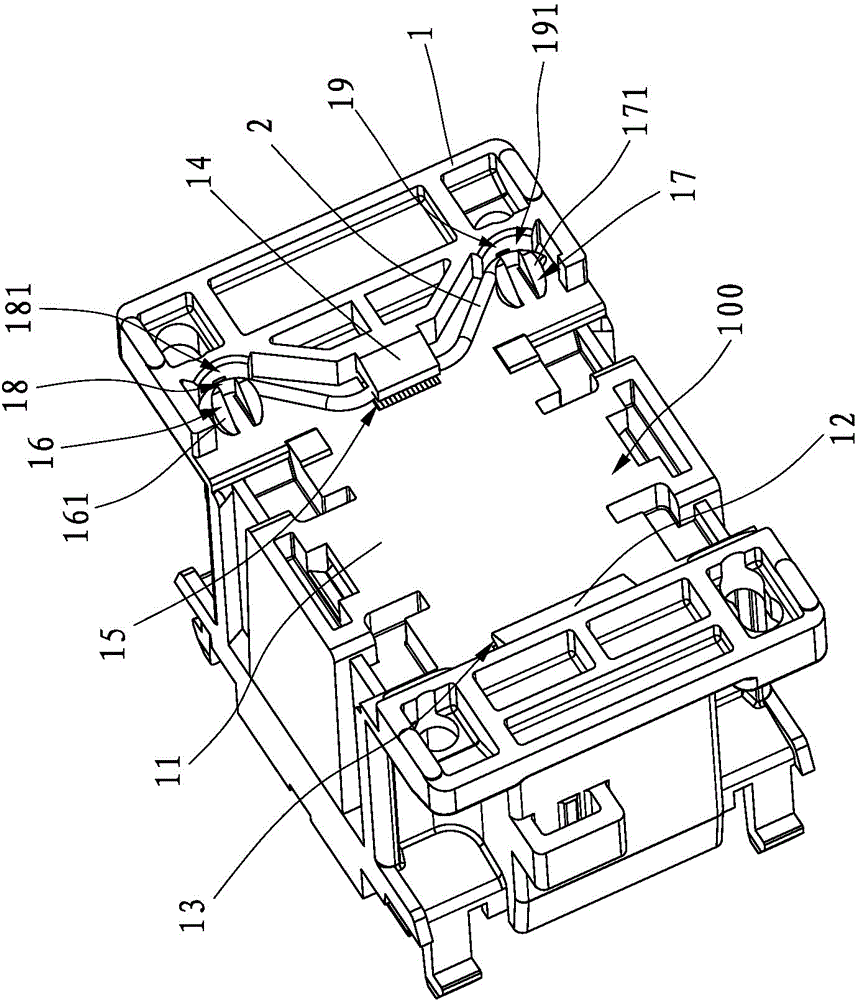
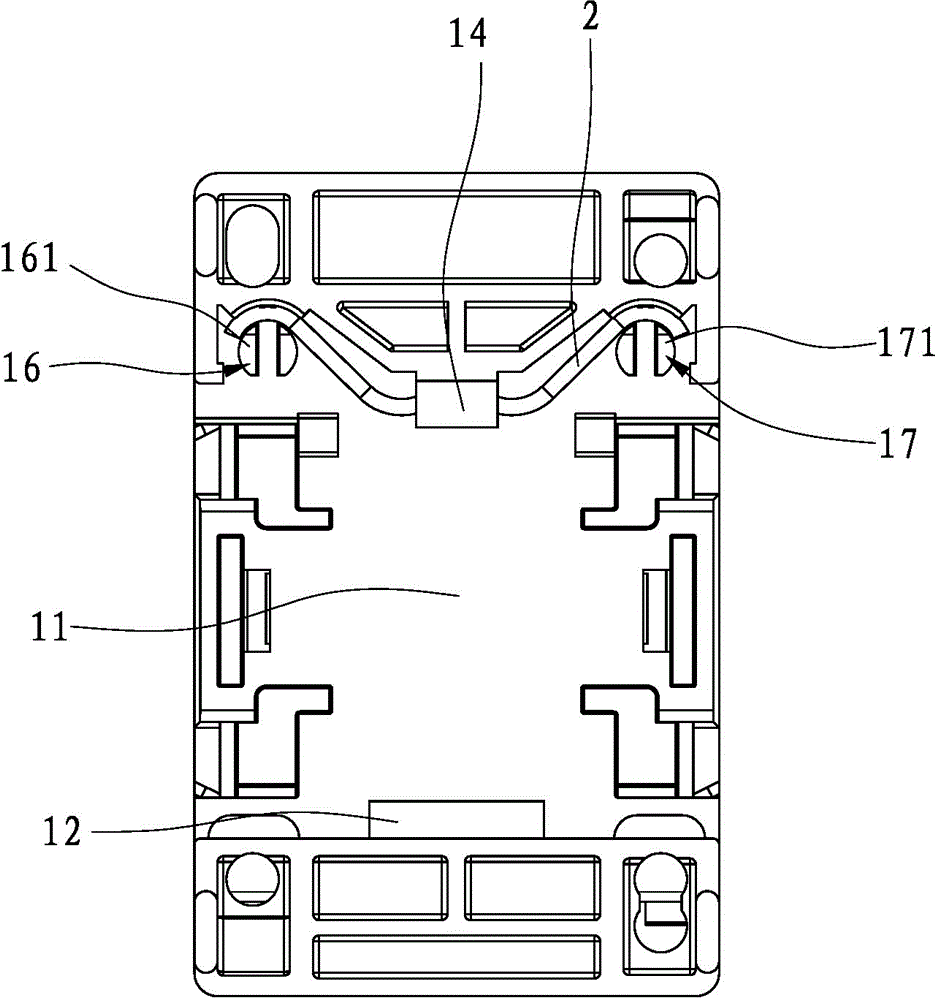
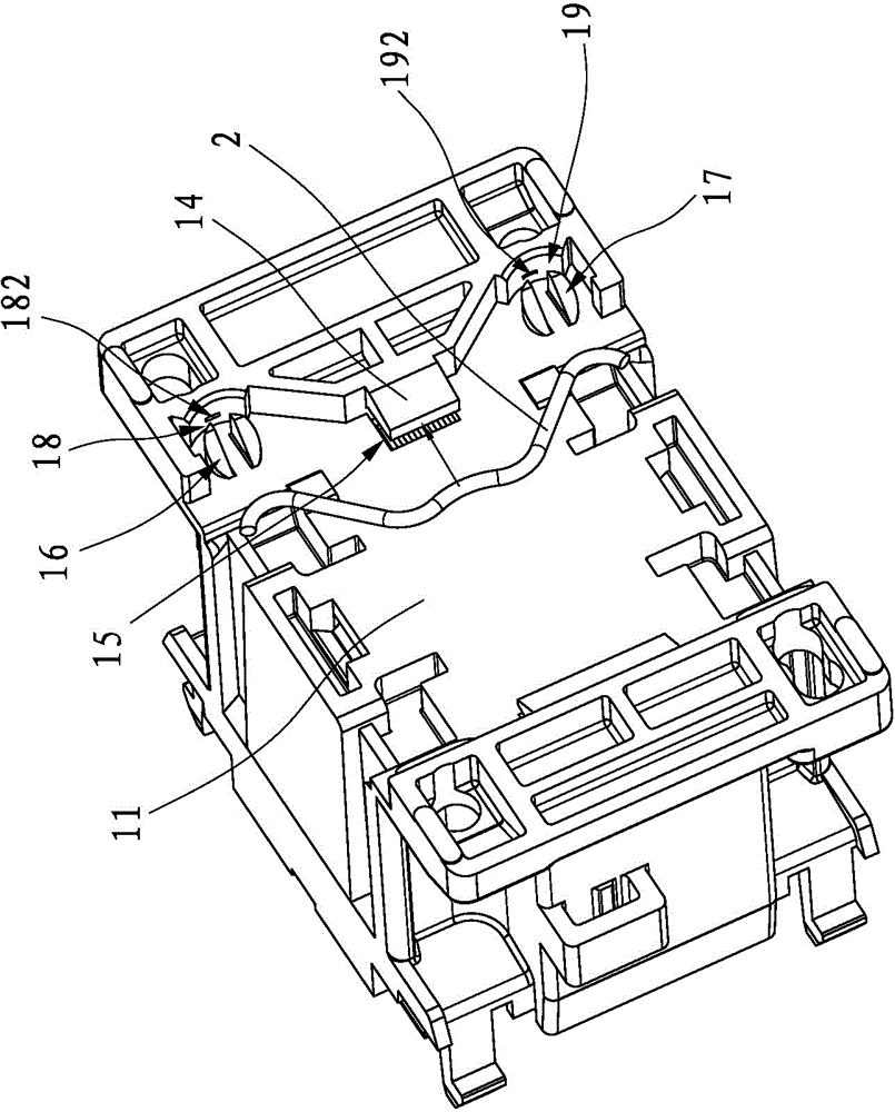
[0041] refer to Figure 1 to Figure 5 As shown, in the guide rail installation structure of an electrical appliance disclosed in the present invention, an installation groove 11 is formed on the base 1 of the electrical appliance 100 , and at least one first fixing buckle 12 is formed on one side of the installation groove 11 . In this embodiment, there is one first fixing buckle 12 . A first slot 13 is formed between the first fixing buckle 12 and the base 1 .
[0042] At least one second fixing buckle 14 is formed on the other side of the installation groove 11 , and a second locking groove 15 is formed between the second fixing buckle 14 and the base 1 .
[0043] Both sides of the second fixing buckle 14 form a first limiting block 16 and a second limiting block 17 respectively, and a first limiting groove 18 is formed between the first ...
PUM
 Abstract
Description
Claims
Application Information