Jig of machining box

A box and fixture technology, applied in the direction of clamping, manufacturing tools, metal processing equipment, etc., can solve the problems of non-parallel processing accuracy of the clamping surface, unusable, non-parallel draft angle, etc., to achieve expansion and adaptability range, saving energy and cost, avoiding slipping and running effects

Active Publication Date: 2014-01-22
成都华川电装有限责任公司
View PDF9 Cites 7 Cited by
  • Summary
  • Abstract
  • Description
  • Claims
  • Application Information

AI Technical Summary

Problems solved by technology

Moreover, sometimes the box does not have enough space to install the pressure plate, nor can it be pressed from top to bottom.
[0003] At present, this method usually uses a clamping method similar to a flat-nose pliers. This method is suitable for single-piece and small-batch production, but the efficiency is low, and because the two clamping surfaces of the box are not parallel or the draft angle of the casting box exists , which directly affects the machining accuracy
[0004] In order to improve the machining accuracy of the box body, it is necessary to complete the processing of the box hole system and the vertical hole mounting surface simultaneously. When the above-mentioned clamping method similar to the flat pliers is used, there are also clamping surfaces that are not parallel or the draft angle of the cast box body is opposite. Influence of machining accuracy

Method used


Image

  • Jig of machining box
  • Jig of machining box
  • Jig of machining box

Examples


Embodiment Construction

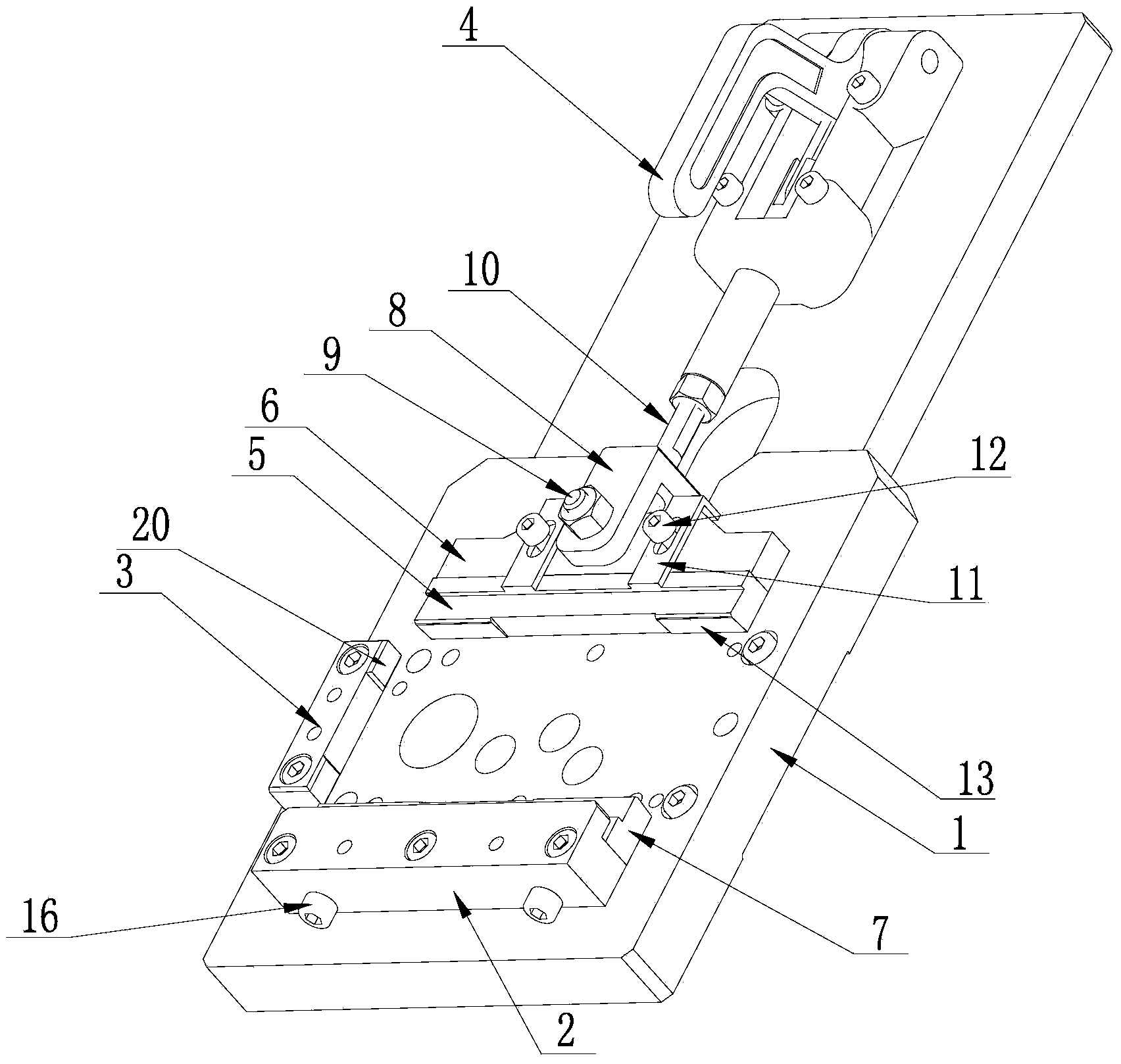
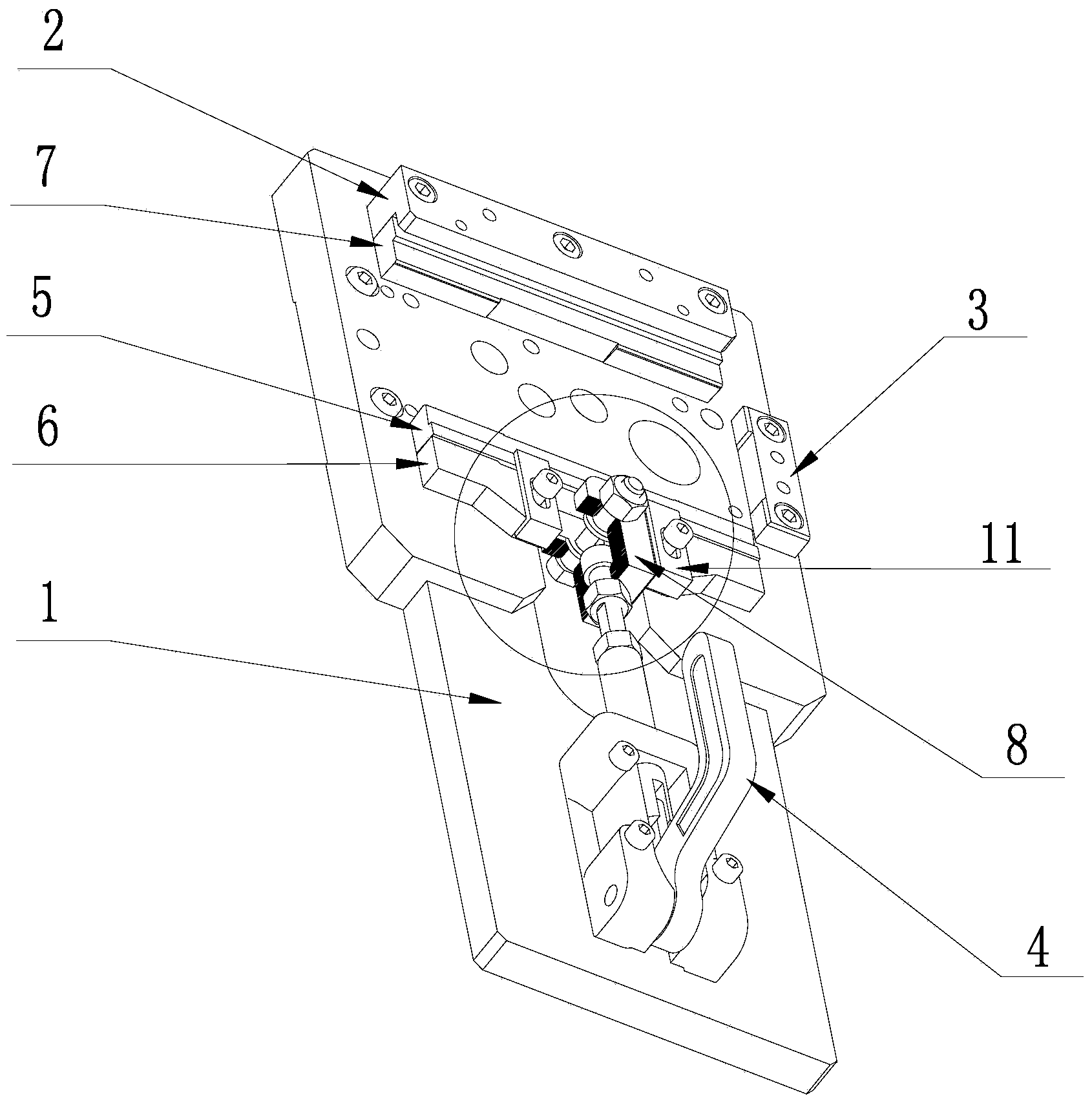
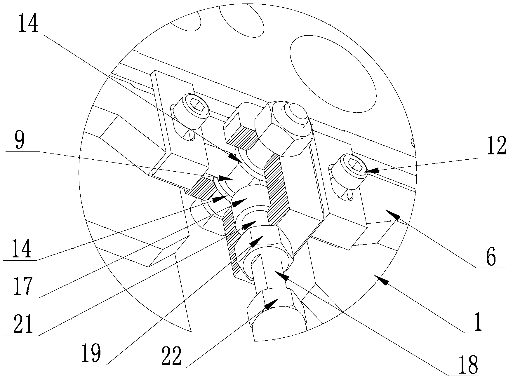
[0024] The present invention will be further described below in conjunction with the accompanying drawings, but the protection scope of the present invention is not limited to the following description.

[0025] Such as Figure 1 to Figure 6 As shown, the machine-added box fixture of the present invention includes a base plate 1, a front baffle, a wedging plate 5 and a power unit. The front baffle is arranged on the front end of the base plate 1, and the power unit is fixed on the base plate 1. The rear end of the wedging plate 5 is placed on the base plate 1, between the front baffle and the power unit, and a transmission device is arranged between the power unit and the wedging plate 5; A left inclined surface 13 inclined in the holding direction, and a right inclined surface 15 whose top end is inclined in the holding direction is provided on the holding surface of the front baffle. During use, the box body is placed on the bottom plate 1, between the wedge plate 5 and the...


PUM


Abstract

The invention discloses a jig of a machining box, wherein the jig solves the problem that a jig of a machining box is not high in clamping reliability. The jig comprises a bottom plate, a front baffle, a wedge pressing plate and a power device. The front baffle is arranged at the front end of the plate surface of the bottom plate, the power device is fixed to the rear end of the plate surface of the bottom plate, the wedge pressing plate is arranged on the bottom plate and located between the front baffle and the power device, and a transmission device is arranged between the power device and the wedge pressing plate; the clamping surface of the wedge pressing plate is provided with a left inclined plane inclined towards the clamping direction, and the clamping surface of the front baffle is provided with a right inclined plane symmetrical to the left inclined plane. The jig of the machining box belongs to the field of jigs. Because of the arrangement of the left inclined plane and the right inclined plane, the box cannot influence the clamping effect due to a casting draft angle; because the wedge pressing plate capable of rotating is arranged, the box cannot influence the clamping effect due to unparallel clamping surfaces, thereby being capable of not influencing machining precision; a quick clamp is adopted to serve as the power device, so energy is saved, and meanwhile the jig is convenient to use.

Description

technical field [0001] The invention relates to the field of clamps, in particular to a reliable clamping machined box clamp. Background technique [0002] The fixture used for machining the installation surface and hole system of the box body can be designed to compress the box body from top to bottom. This method is simple and convenient; The hole system of the box body, and then use the hole system to locate and press it, and then process the mounting surface of the vertical hole system; on the contrary, tighten the hole system of the box body, process the mounting surface first, and then process the hole system after pressing the box mounting surface; Both of these methods do not complete the processing of the box hole system and the vertical hole mounting surface after clamping the box at one time. Moreover, sometimes the box body does not have enough space to install the pressure plate, nor can it be pressed from top to bottom. [0003] At present, this method usuall...

Claims


Application Information

Patent Timeline
Patent Type & Authority Applications(China)
IPC IPC(8): B23Q3/06
CPCB23Q3/062B23Q3/066
Inventor 徐春平刘洋唐兴伟李贵树李华峰
Owner 成都华川电装有限责任公司
Why Eureka
Try Eureka