Fuel cell internal temperature-heat flux density distribution measurement insert

A heat flow density and fuel cell technology, applied in fuel cells, fuel cell additives, thermometers, etc., can solve the problem that the heat flow density distribution of fuel cells cannot be accurately reflected, increase the number of disassembly and assembly of fuel cells, and affect the accuracy of temperature measurement, etc. problems, to achieve the effect of simplifying the steps of measuring the internal temperature and heat flow density distribution of the fuel cell, ensuring the performance, and making the production convenient.

Inactive Publication Date: 2015-03-11
BEIJING UNIV OF TECH
View PDF4 Cites 5 Cited by
  • Summary
  • Abstract
  • Description
  • Claims
  • Application Information

AI Technical Summary

Benefits of technology

This new technology allows us to accurately determine both the amount of thermal energy (the rate at which it releases or absorbs) inside each part of an individual fuel cell without having to remove any parts from its environment during testing. It uses specialized equipment that measures this distributed data on real world conditions while keeping them stable over long periods of use. Overall, these technical improvements make better understanding how different types of fuels behave differently under specific environmental factors improving their overall efficiency and reliability within power systems.

Problems solved by technology

This patented describes various technical problem addressed in the patents: how to efficiently convert chemical reactions into electrical power through fuel cells that contain tiny electronic components called molecules (molecular fuels) at specific locations within their interior space. Existing techniques involve embedding small devices like microelectronic elements near certain points where there may occur localized high temperatures caused by the combustion process itself. These conventional approaches often result in variations in temperature distributions throughout the entirety of the system, making accurate analysis challenges even more complex than desired.

Method used


Image

  • Fuel cell internal temperature-heat flux density distribution measurement insert
  • Fuel cell internal temperature-heat flux density distribution measurement insert
  • Fuel cell internal temperature-heat flux density distribution measurement insert

Examples


Embodiment Construction

[0034] The present invention will be further described below in conjunction with the accompanying drawings.

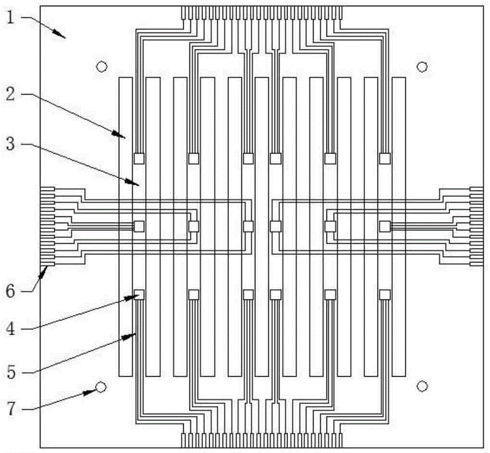
[0035] refer to figure 1As shown, the present invention includes a conductive substrate 1, a leaky seam 2, a rib 3, a temperature-heat flux joint measurement sensor 4, a lead wire 5, a pin 6, and a positioning hole 7; the leaky seam 2 and the rib 3 are arranged on the conductive substrate 1 It is the same shape and size as the flow channel and ridge on the flow field plate of the fuel cell under test, and its positions correspond to each other. A temperature-heat flux joint measurement sensor 4 is arranged on the rib 3; one end of the lead wire 5 is connected to the temperature-heat flow The density joint measurement sensor 4 is connected, and the other end extends to the edge of the conductive substrate 1 for transmitting the electrical signal generated by the temperature-heat flux joint measurement sensor 4; the pin 6 is arranged on the edge of the conductive substra...


PUM

PropertyMeasurementUnit
Widthaaaaaaaaaa

Abstract

A fuel cell internal temperature-heat flux density distribution measurement insert is a fuel cell internal temperature-heat flux density distribution measurement device, a leakage seam and a rib which are corresponding to a fuel cell flow field plate flow passage and ridge are arranged on a conductive substrate, and a temperature-heat flux density combined measurement sensor is arranged on the rib; the temperature-heat flux density combined measurement sensor is prepared by vacuum evaporation coating method, and comprises five layers of thin films. A leading wire is also prepared by the vacuum evaporation coating method, is used to transmit electrical signals, and extends to the flow field plate edge to form a lead foot by magnifying to facilitate connecting with external connection data acquisition equipment. The fuel cell internal temperature-heat flux density distribution measurement insert realizes the synchronous online measurement of fuel cell internal temperature distribution and heat flux density distribution can be used as a independent component to be arranged in a fuel cell without special transformation of the fuel cell structure, and is wide in range of application, and suitable for a fuel cell flow field plate with a parallel flow passage, a serpentine flow passage, an interleaved flow passage or a flow passage with other shape.

Description


Claims


Application Information

Patent Timeline
Owner BEIJING UNIV OF TECH
Why Eureka
Try Eureka