Motor, magnet ring magnetizing tool and magnetizing method of motor

A magnetic ring and tooling technology, applied in electromechanical devices, circuits, magnetic objects, etc., can solve the problems affecting motor performance, the positional deviation of Hall components in the circumferential direction, and the influence of the position accuracy of Hall components. The effect of improving performance

Active Publication Date: 2015-03-11
GUANGDONG WELLING ELECTRIC MACHINE MFG
View PDF4 Cites 2 Cited by
  • Summary
  • Abstract
  • Description
  • Claims
  • Application Information

AI Technical Summary

Problems solved by technology

[0003] However, due to structural limitations, the Hall component cannot be directly installed on the stator component, but needs to be installed on the rear end cover. In this way, when the processing accuracy or installation accuracy of the rear end cover is not high, the position accuracy of the Hall component will also be affected. The position of the Hall assembly relative to the stator assembly in the circumferential direction of the stator assembly is deviated, which affects the performance of the motor

Method used


Image

  • Motor, magnet ring magnetizing tool and magnetizing method of motor
  • Motor, magnet ring magnetizing tool and magnetizing method of motor
  • Motor, magnet ring magnetizing tool and magnetizing method of motor

Examples


Embodiment Construction

[0031] Embodiments of the present invention are described in detail below, examples of which are shown in the drawings, wherein the same or similar reference numerals designate the same or similar elements or elements having the same or similar functions throughout. The embodiments described below by referring to the figures are exemplary and are intended to explain the present invention and should not be construed as limiting the present invention.

[0032] A motor 1 according to an embodiment of the present invention is described below with reference to the drawings.

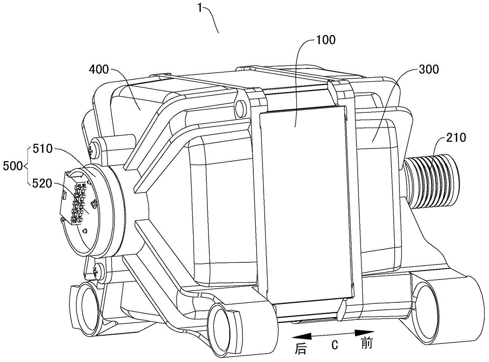
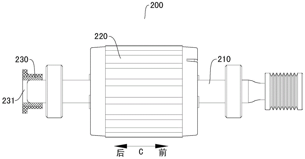
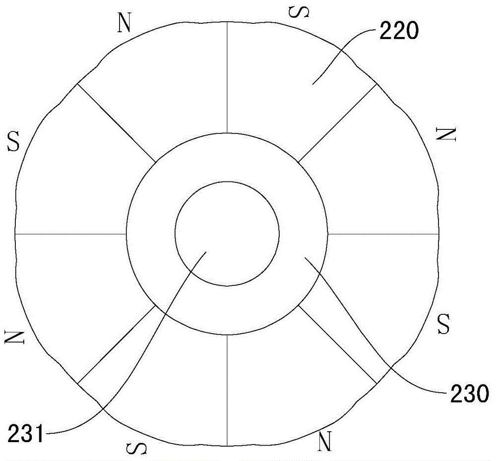
[0033] Such as Figure 1-Figure 5 As shown, the motor 1 according to the embodiment of the present invention includes a stator assembly 100 , a rotor assembly 200 , a front end cover 300 , a rear end cover 400 and a Hall assembly 500 .

[0034] The axial direction of the stator assembly 100 is oriented along the front-rear direction (the front-rear direction is as figure 1 , figure 2 and Figure 7 indicat...


PUM


Abstract

The invention discloses a motor, a magnet ring magnetizing tool and a magnetizing method of the motor. The motor comprises a stator component, a rotor component, a front-end cover, a rear-end cover and a Hall component; the rotor component comprises a rotor shaft as well as rotor magnet poles and magnet rings which are sleeved on the rotor shaft; the magnet rings are located at the rear end of the rotor shaft and partially suspended to form a central positioning hole; the front-end cover is installed at the front end of the stator component; the rear-end cover is installed at the rear end of the stator component; a central penetrating hole and a circumferential positioning hole are formed on the rear-end cover; the Hall component is installed on the rear-end cover and provided with an assembling column; and the assembling column is matched in the circumferential positioning hole so as to position the Hall component in the circumferential direction of the stator component. The motor can guarantee the special position relation of the Hall component and the stator component in the circumferential direction of the stator component and has the advantages of excellent performance and reliability and the like.

Description

technical field [0001] The invention relates to the technical field of electric appliance manufacturing, in particular to a motor, a magnetic ring magnetization tool for the motor and a magnetization method for the motor. Background technique [0002] In the motor in the related art, since the number of poles of the magnetic ring is equal to the number of rotor poles, the position of the magnetic ring represents the position of the rotor magnetic pole, so that the magnetic ring and the rotor magnetic pole are magnetized together, so that the magnetic ring has a specific position relative to the rotor magnetic pole in the circumferential direction of the stator. location relationship. The Hall component maintains a specific positional relationship with the stator component in the circumferential direction of the stator component. By detecting the position of the magnetic ring, the position of the rotor component relative to the stator component is obtained, and the stator com...

Claims


Application Information

Patent Timeline
Patent Type & Authority Applications(China)
IPC IPC(8): H02K29/08H01F13/00
Inventor 王松井赟何汉潮陈勋彬
Owner GUANGDONG WELLING ELECTRIC MACHINE MFG
Why Eureka
Try Eureka