
Filter element and filter system with a filter element

A filter system and filter element technology, applied in the field of filter systems with filter elements, to achieve the effects of protection from pollution, high service life and reduced pressure loss

Active Publication Date: 2015-03-18
MANN HUMMEL GMBH
View PDF6 Cites 2 Cited by
  • Summary
  • Abstract
  • Description
  • Claims
  • Application Information

AI Technical Summary

Problems solved by technology

[0004] A conically shaped filter element is known from document EP 1558360 B1, however, due to the conical shape (which opens at an angle opposite the discharge direction of the filter system) it requires a greater installation space
Folded secondary elements are also known, but require additional installation space compared to secondary elements with a flat filter medium

Method used


Image

  • Filter element and filter system with a filter element
  • Filter element and filter system with a filter element
  • Filter element and filter system with a filter element

Examples


Embodiment Construction

[0044] In the drawings, identical or similar components are numbered with the same reference numerals. The drawings show examples only and are not to be construed as limiting.

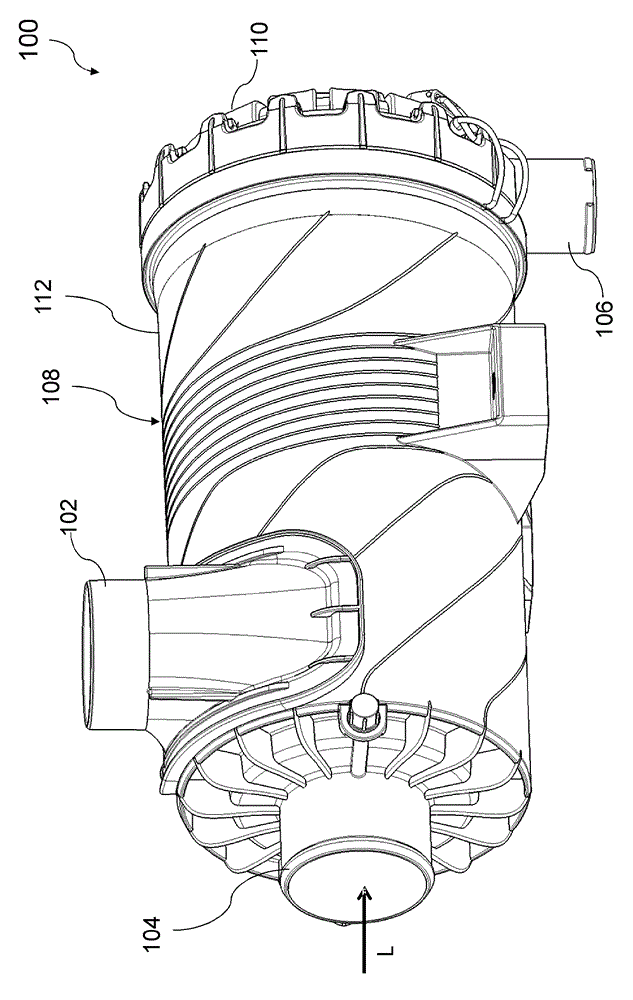
[0045] figure 1 Shows a perspective view of a secondary filter system 100 with a cyclone separator 36 according to an embodiment of the invention, with a tangential inlet 102, a central outlet at the housing end side Dirt exits portion 104 and bottom side from portion 106 . A circular filter structure is shown, which contains a housing 108 which has a housing wall 112 and is closed with a cover 110 (for example with a screw connection or a bayonet connection). When used as an air filter system, dust-laden air flows into the inlet 102 which is arranged tangentially with respect to the air filter element installed inside, so that the air is passed in the interior of the housing 108 by the inflow at the filter element The guard is placed in a swivel motion. The filter element and the inflow protection...


PUM


Abstract

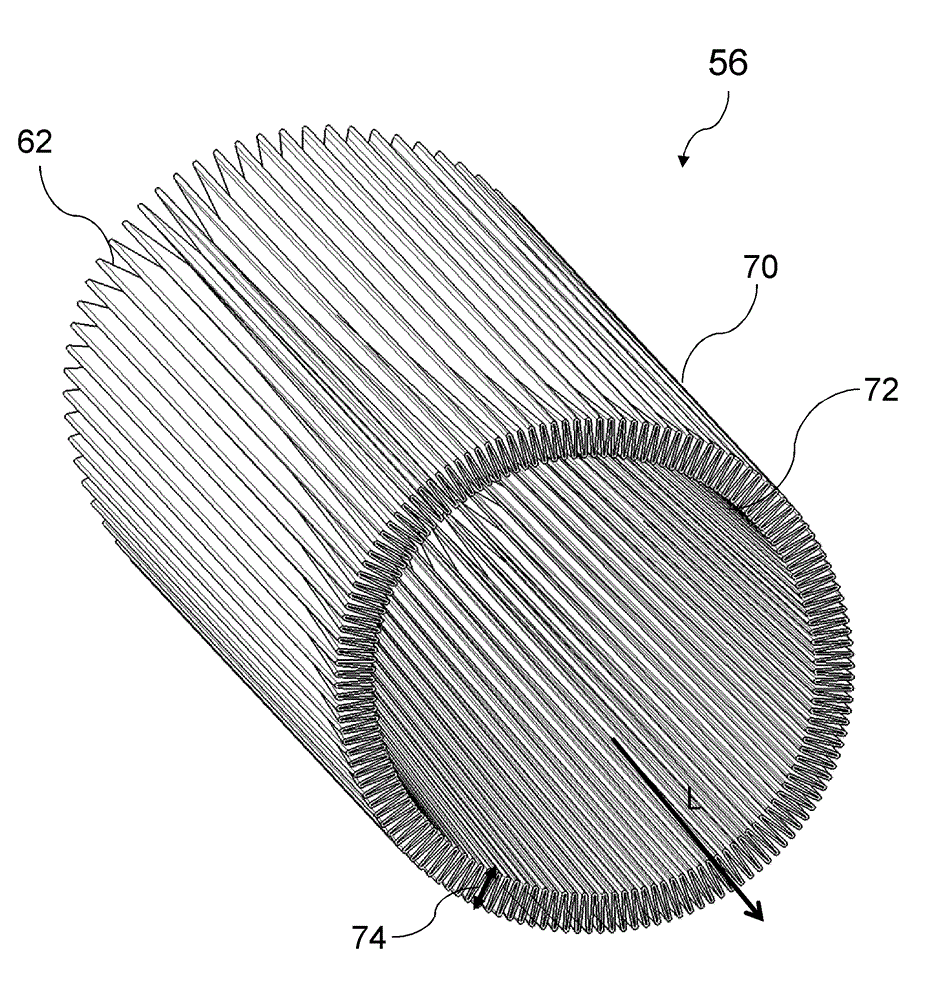
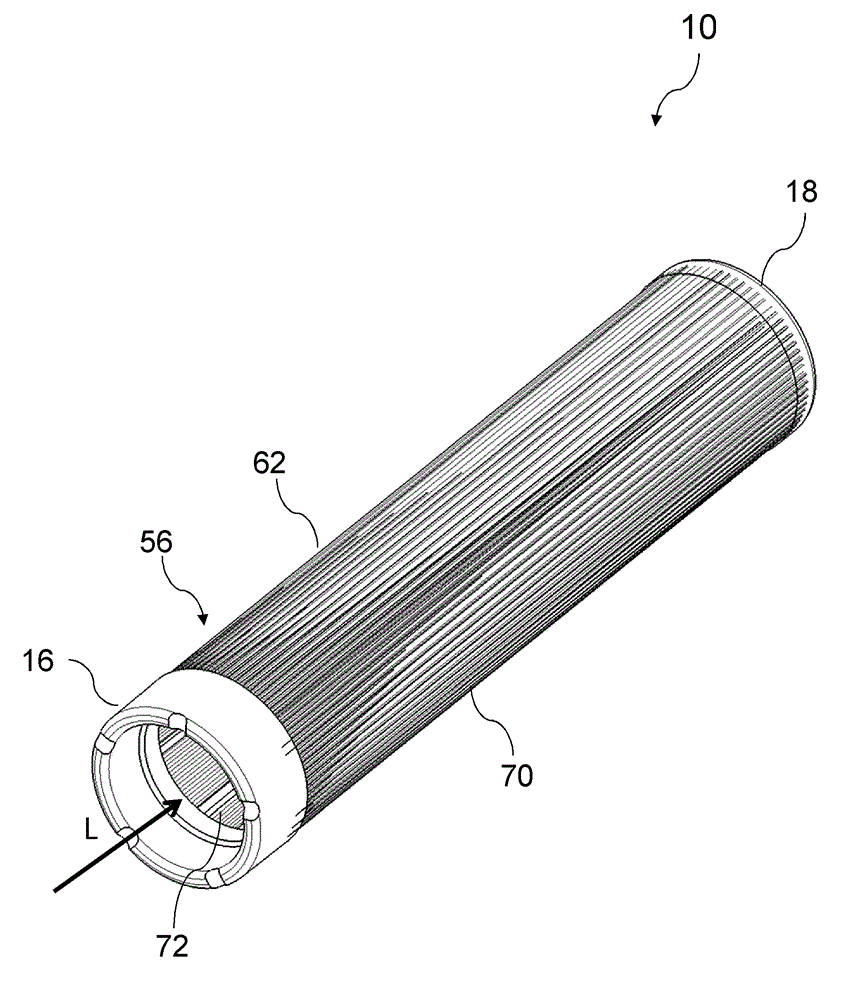
A filter element has a filter body having a longitudinal axis, wherein the filter body has a first end with a first end face and a second end with a second end face opposite the first end in direction of the longitudinal axis. The filter body is provided with inner and outer circumferential surfaces permeable for a medium to be filtered. A first end disk is arranged at the first end face and a second end disk is arranged at the second end face. The outer circumferential surface of the filter body has at least one fluid-tight area that is impermeable for the medium to be filtered. The fluid-tight area is an incoming flow protector or an improper handling protector resting on the outer circumferential surface.

Description

technical field [0001] The invention relates to a filter system with a filter element, especially for use as an air filter for an internal combustion engine, and to a filter element for installation in such a filter system. Background technique [0002] The construction of filter systems in which circular filter elements are used is known from the prior art. In use, the round filter element often flows from the outside to the inside, the filtered fluid being guided from the cylindrical interior through openings in the cover or base of the round filter element to the outlet of the filter housing. The diameter of the outlet opening in the cover of the circular filter element is limited by the diameter of the interior of the filter element. The diameter of the outlet opening is obtained from the diameter of the filter element minus the fold height of the filter medium used. [0003] On the one hand, with the same external dimensions, the greatest possible fold height allows a...

Claims


Application Information

Patent Timeline
IPC IPC(8): B01D46/52B01D46/00F02M35/024
CPCB01D46/522B01D2275/201B01D46/0024B01D46/2411B01D39/18F02M35/0209F02M35/0245F02M35/02483F02M35/084B01D46/64
Inventor M.考夫曼K-D.鲁兰I.马尔顿
Owner MANN HUMMEL GMBH
Learn More