Rear stop and no-go gauge device of bending machine

A back gauge and bending machine technology, which is applied in the field of back gauge stop gauge devices for press brakes, can solve the problems of poor adjustment accuracy, inconvenient operation, and high processing accuracy requirements, achieve simple assembly, and reduce manufacturing and labor costs. , the effect of flexible operation

Inactive Publication Date:
View PDF0 Cites 3 Cited by
  • Summary
  • Abstract
  • Description
  • Claims
  • Application Information

AI Technical Summary

Problems solved by technology

[0003] The purpose of the present invention is to solve the problems of inconvenient operation, poor adjustment accuracy and high processing accuracy requirements of the existing bending machine stop gauge device, and provide a new type of back gauge stop gauge device for bending machines

Method used


Image

  • Rear stop and no-go gauge device of bending machine
  • Rear stop and no-go gauge device of bending machine
  • Rear stop and no-go gauge device of bending machine

Examples


Embodiment Construction

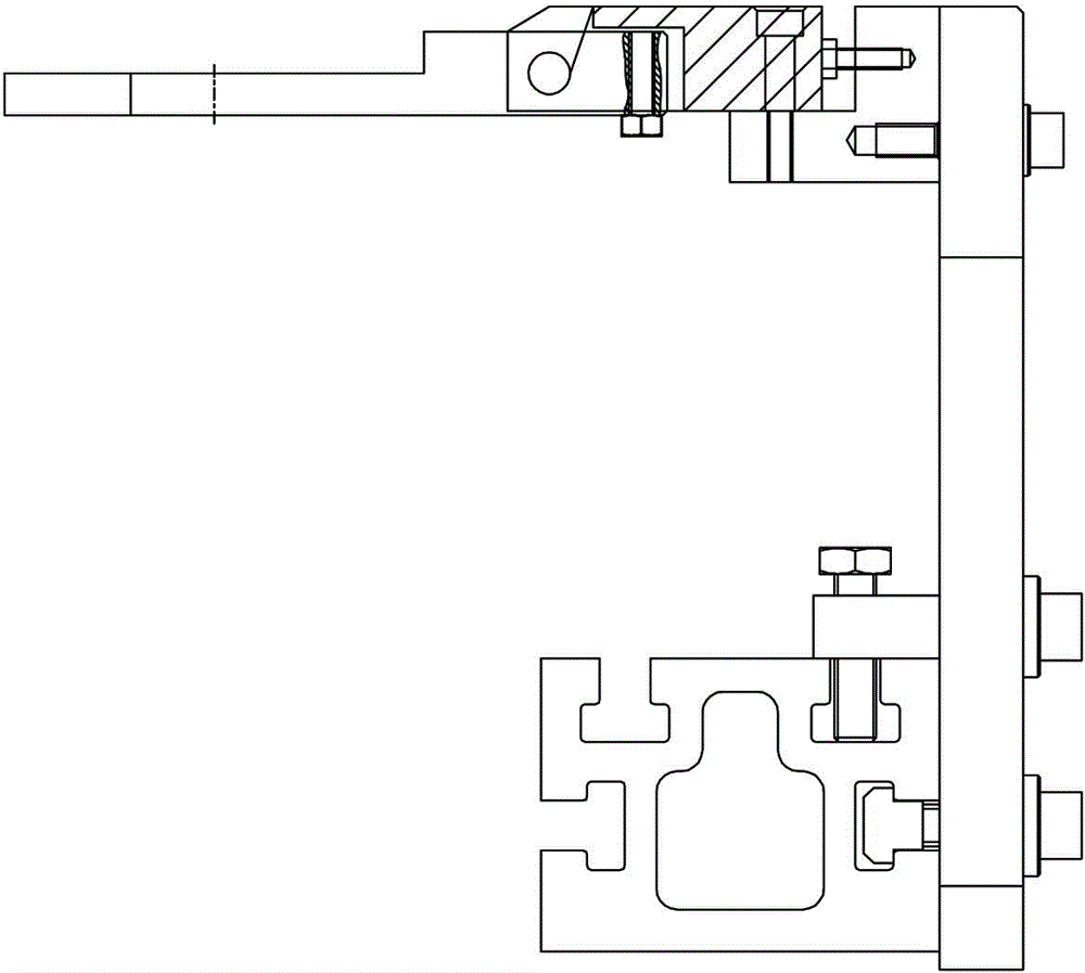
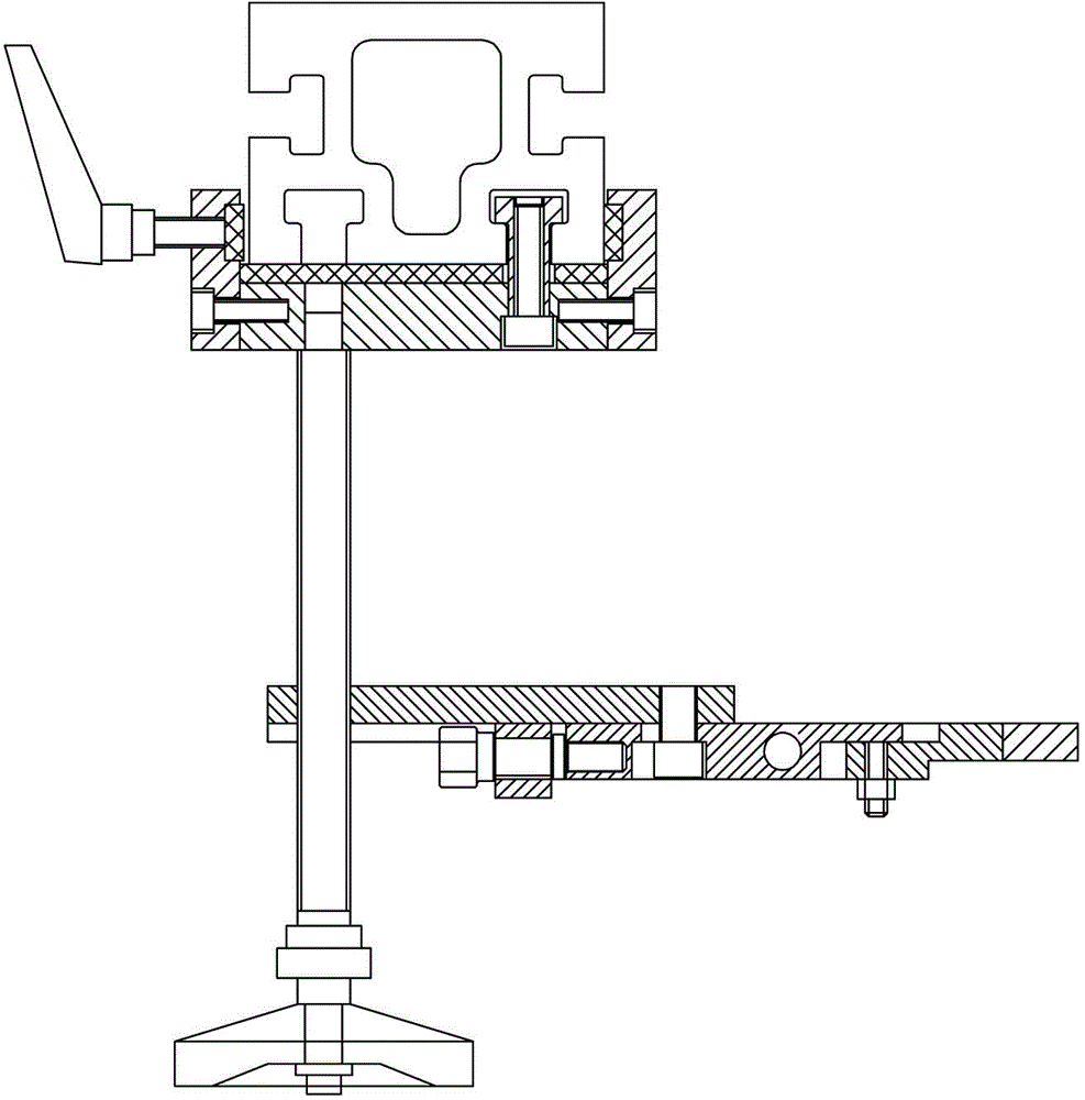
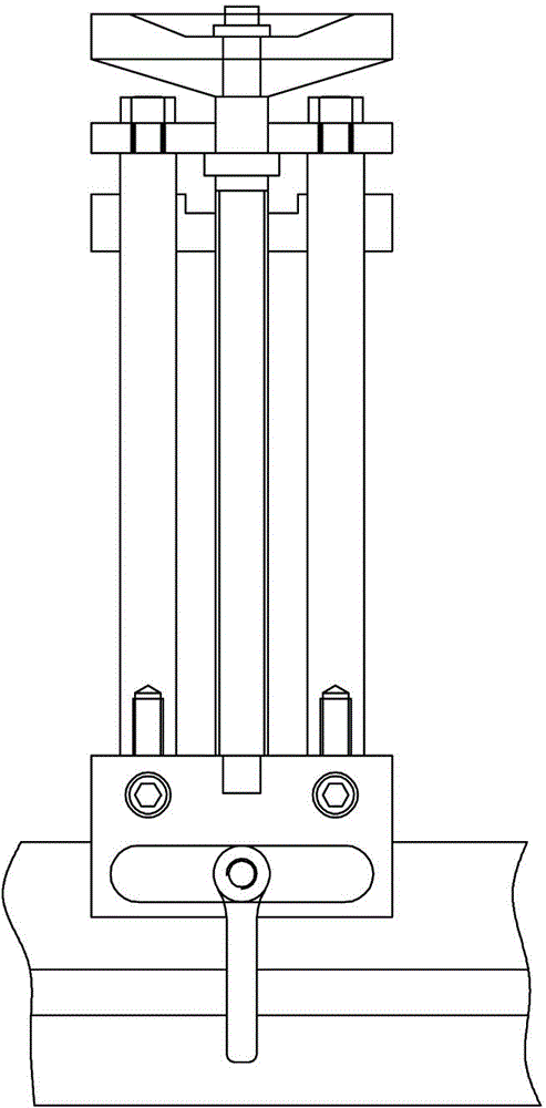
[0016] see Figure 4 , the present invention includes a stopper block, the stopper block is installed on a lifting seat 4, in particular: the lifting seat 4 is provided with two front and rear through holes, and a nut 5 is fixed in the front through hole to fit a transmission wire Rod 6, the rear through hole is mounted on a vertical guide column 10, and the upper and lower ends of the guide column 10 are respectively fixed with a top plate 7 and a base 15, and the top plate 7 is provided with the front through hole on the lifting seat 4. The shaft holes arranged coaxially, the shaft holes support the upper end of the transmission screw rod 6, and the upper end of the transmission screw rod 6 extends out of the top plate 7, the outer mounting retaining ring 8 and the rotating hand wheel 9.

[0017] In this embodiment, the material stopper is formed by connecting the movable stopper 1 and the fixed stopper 3 with the pin shaft 2 , and the fixed stopper 3 is installed on the lif...


PUM


Abstract

The invention relates to the improved technology of sheet-metal working equipment, in particular to a rear stop and no-go gauge device of a bending machine. The stop and no-go gauge device comprises a stop block arranged on a lifting base and is characterized in that a front penetrating hole and a rear penetrating hole are formed on the lifting base; a driving screw rod matching with a screw is fixedly installed in the front penetrating hole and a vertical guide column is penetrated in the rear penetrating hole; a top plate and a base are fixedly installed at the upper and lower ends of the guide column; an axial hole coaxial to the front penetrating hole on the lifting base is formed on the top plate; the axial hole is used for supporting the polished part at the upper end of the driving screw rod; a retainer ring and a rotating hand wheel are arranged at the upper end of the driving screw rod and the external part extended out of the top plate. The rear stop and no-go gauge device solves problems such as inconvenient operation, worse regulation precision and high processing precision in the rear stop and no-go gauge device of the present bending machine; and a new rear stop and no-go gauge device of the bending machine is provided.

Description

technical field [0001] The invention relates to the improvement technology of sheet metal processing equipment, in particular to a rear stop gauge device of a bending machine. Background technique [0002] The stop gauge device in the back gauge mechanism of ordinary hydraulic bending machine is a necessary part for positioning the sheet and ensuring the contour accuracy of the workpiece. Generally, the stop block in the stop gauge device needs to be able to move up and down to a suitable height position according to the shape and size of the bending workpiece. At present, there are two types of rear stop gauge devices in ordinary hydraulic bending: L-shaped plate type stop gauge (see figure 1 ) and three-bar stop gauge (see figure 2 , 3 ). Although the production cost of the L-shaped plate stop gauge is low, the parts are few, and the structure is simple, its disadvantages are also very obvious: first, because the movable material stop plate and the lifting plate conne...

Claims


Application Information

Patent Timeline
Patent Type & Authority Applications(China)
IPC IPC(8): B21D11/22
CPCB21D11/22
Inventor 黄俊何从磊
Why Eureka
Try Eureka