Supercharge Your Innovation With Domain-Expert AI Agents!

Slicing machine with reversing device

一种切片机、枢转的技术,应用在取样装置、测量装置、传动装置等方向,能够解决提高成本、多零部件、增加传动单元复杂性等问题,达到减少构件数量、降低成本的效果

Active Publication Date: 2015-03-18
LEICA MICROSYST LTD SHANGHAI SHANGHAI
View PDF5 Cites 14 Cited by
  • Summary
  • Abstract
  • Description
  • Claims
  • Application Information

AI Technical Summary

Problems solved by technology

The disadvantage of this prior art is that at least three intermediate gears (or idler gears) are required for the transmission unit
This will obviously increase the complexity of the transmission unit and require more components, thereby increasing the cost

Method used


Image

  • Slicing machine with reversing device
  • Slicing machine with reversing device
  • Slicing machine with reversing device

Examples


Embodiment Construction

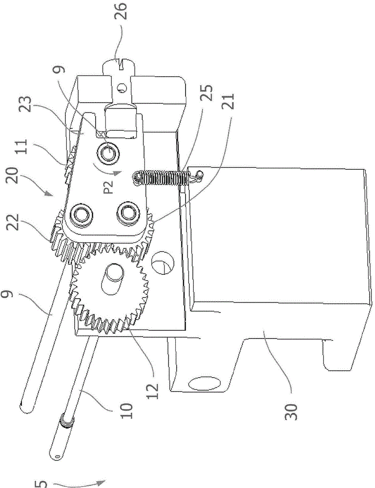
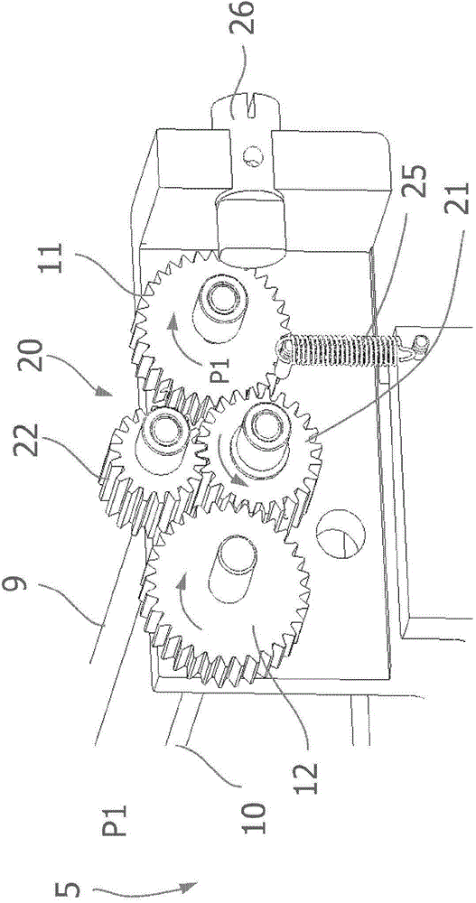
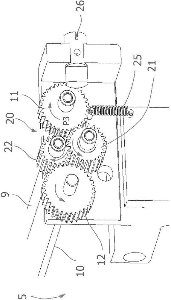
[0025] figure 1 A schematic perspective view of details of the microtome 5 is shown. figure 2 shows the transmission unit in the first position, and image 3 The transmission unit is shown in the second position.

[0026] see figure 1 , the slicer 5 includes a first shaft 9, and a first gear 11 is non-rotatably connected to one end of the first shaft. The first axis 9 can be figure 1 - The hand wheel not shown in 3 is directly or indirectly driven. The handwheel may be a handwheel for rough infeed of the sample.

[0027] In addition, the microtome 5 comprises a second shaft 10, at one end of which a second gear 12 is non-rotatably connected. Thus, the second axis 10 is used to perform a rough feed and / or to generate a cutting movement. The cutting unit is figure 1 -3 is not shown. The first and second shafts 9, 10 are mounted in the frame 30 by bearing units (not shown). The first and second shafts 9 , 10 and the first and second gear wheels 11 , 12 mounted thereon ...


PUM


Abstract

A microtome has first and second shafts at different fixed positions, wherein the first shaft may be rotated by a hand wheel. The shafts carry first and second gear wheels, respectively. A transmission unit couples the two gear wheels to each other so that the second shaft can be driven to rotate by the first shaft, and a shift unit for pivotably shifting the transmission unit between first and second positions. The two shafts rotate in the same direction when the transmission unit is in the first position, and in opposite directions when the transmission unit is in the second position. The transmission unit includes first and second idler gears meshing constantly with each other. The two shafts are coupled by only one of the idler gears when the transmission unit is in the first position, and by both idler gears when the transmission unit is in the second position.

Description

technical field [0001] The invention relates to a microtome which is manually driven by means of at least one handwheel for the production of thin slices. Background technique [0002] A microtome is used to cut thin slices from the sample. These sections are then placed on coverslips, processed appropriately, and then examined under a microscope. [0003] In the known rotary microtome, the cutting unit is driven by turning at least one handwheel. Some operators feel more comfortable turning the handwheel clockwise, while others feel more comfortable turning it counterclockwise. Therefore, there are two kinds of slicers on the market, one of which has a handwheel that needs to be turned clockwise, and one of which has a handwheel that needs to be turned counterclockwise. Customers must choose one of these two options at the time of purchase. The direction of rotation can only be changed afterwards by a technician through extensive and cumbersome modifications. [0004] ...

Claims


Application Information

Patent Timeline
Patent Type & Authority Applications(China)
IPC IPC(8): B26D5/10G01N1/06
CPCG01N1/06F16H3/34F16H3/40F16H1/20G01N2001/065Y10T74/19172
Inventor 范哲光周啸
Owner LEICA MICROSYST LTD SHANGHAI SHANGHAI
Features
  • R&D
  • Intellectual Property
  • Life Sciences
  • Materials
  • Tech Scout
  • Unparalleled Data Quality
  • Higher Quality Content
  • 60% Fewer Hallucinations
Learn More