Heat tube with ultra-thin flat plate type capillary structure

A capillary structure, flat plate technology, applied in the field of heat pipes with ultra-thin flat capillary structure, can solve the problems of large contact thermal resistance, filling, steam channel heat pipes are easy to sag, etc., and achieve the effect of small contact thermal resistance of depressions

Inactive Publication Date: 2015-03-18
白豪
View PDF0 Cites 4 Cited by
  • Summary
  • Abstract
  • Description
  • Claims
  • Application Information

AI Technical Summary

Problems solved by technology

[0003]However, because the thickness of the ultra-thin heat pipe needs to be thinned, the internal capillary structure is also thinner in thickness, otherwise it will not be able to form enough airflow in the heat pipe aisle
However, the capillary structure that is too thin cannot be filled in the gap between the mandrel and the heat pipe wall in the manufacturing process, because the gap is relatively small, and the resistance generated when the metal powder is filled is large, so it cannot be processed.
Therefore, in the past, the powder capillary structure in the ultra-thin heat pipe is only formed in a local position in the heat pipe and has not been thinned. Therefore, it is known that the powder capillary structure of the ultra-thin heat pipe is not easy to fill the sectional surface of the ultra-thin heat pipe, and its capillary structure cannot be improved. The evaporating and condensing surface and the truncated transmission surface, at the same time, cannot maintain enough vapor channels and the internal support structure with poor strength makes the heat pipe easy to sag and has a large contact thermal resistance, which will not further improve its heat transfer efficiency.

Method used


Image

  • Heat tube with ultra-thin flat plate type capillary structure
  • Heat tube with ultra-thin flat plate type capillary structure
  • Heat tube with ultra-thin flat plate type capillary structure

Examples


Embodiment Construction

[0050] In order to further disclose the features and technical contents of the present invention, please refer to the following detailed description of the present invention and the accompanying drawings. However, the accompanying drawings are only for reference and description, not for limiting the present invention.

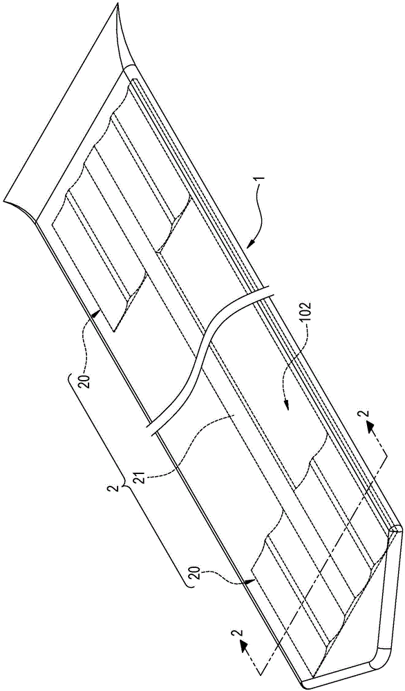
[0051] see figure 1 , is a schematic diagram of the three-dimensional appearance of the present invention. The present invention provides a heat pipe with an ultra-thin flat capillary structure, comprising a flat hollow shell 1 and at least one capillary structure 2 disposed in the shell 1 and in contact with the inner wall of the shell 1; wherein:

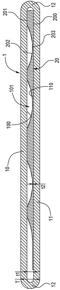
[0052] like figure 1 and figure 2 As shown, the casing 1 can be formed into the flat shape by a process such as flattening, and its outer contour thickness T can be pressed below 0.5 mm. In the embodiment of the present invention, the casing 1 has an upper wall 10 and a lower wall 11 opposite to each other at a...


PUM


Abstract

The invention discloses a heat tube with an ultra-thin flat plate type capillary structure. The heat tube comprises a shell and the capillary structure, wherein the capillary structure is arranged in the shell and comprises heat exchange areas and a liquid transmission passage which is connected between the heat exchange areas, and each heat exchange area is divided into an evaporation part and a condensation part; each heat exchange area is respectively provided with a flat surface and an extrusion surface which is opposite to the flat surface, a plurality of long narrow concave surfaces which are arranged at intervals are formed on the extrusion surfaces, steam flow passages are formed in the shell by the concave surfaces, long narrow capillary organization communication areas are formed by the concave surfaces and the flat surfaces, and hollow areas which are located at two sides of the liquid transmission passage are formed in the shell between the heat exchange areas. According to the heat tube with the ultra-thin flat plate type capillary structure, disclosed by the invention, enough space is provided for carrying out heat exchange of evaporation and condensation, due to an inner supporting structure which is maximum in capillary surface area and truncation transmission surface and is better in strength, the heat tube does not easily concave, the contact heat resistance is smaller, and the effect of enabling a heat conductor to be ultra-thin can be achieved.

Description

technical field [0001] The invention relates to a thinned heat pipe, in particular to a heat pipe with an ultra-thin flat capillary structure. Background technique [0002] Since many 3C electronic products are now designed to be light, thin, short, and small, the heat pipes that serve as their internal heat dissipation or heat conduction functions also need to be thinned, which is like the birth of ultra-thin heat pipes (with a thickness of about 1.5mm or less). [0003] However, since the thickness of the ultra-thin heat pipe needs to be thinned, the capillary structure inside the ultra-thin heat pipe is also thinner in thickness, otherwise, an airflow channel with sufficient space cannot be formed in the heat pipe. However, the too thin capillary structure cannot be filled in the gap between the mandrel and the heat pipe wall in the manufacturing process, because the gap is relatively small, and the resistance generated when the metal powder is filled is large, so it cann...

Claims


Application Information

Patent Timeline
Patent Type & Authority Applications(China)
IPC IPC(8): F28D15/04
Inventor 白豪
Owner 白豪
Why Eureka
Try Eureka