Power transmission device and image forming apparatus including the same

A technology for transmitting devices and images, which is applied to mechanical drive clutches, electrical recording processes using charge patterns, and equipment using electrical recording processes using charge patterns, etc. To achieve the effect of improving assembly performance

Active Publication Date: 2015-03-18
RICOH KK
View PDF5 Cites 3 Cited by
  • Summary
  • Abstract
  • Description
  • Claims
  • Application Information

AI Technical Summary

Problems solved by technology

Therefore, it is difficult to mesh the input internal gear of the intermediate transmission part with the output external gear on the output shaft
In addition, it is also difficult to fit one end of the above-mentioned fall-off prevention member into the fitting groove of the in

Method used


Image

  • Power transmission device and image forming apparatus including the same
  • Power transmission device and image forming apparatus including the same
  • Power transmission device and image forming apparatus including the same

Examples


Example Embodiment

[0026] [Embodiment 1]

[0027] Hereinafter, a first embodiment in which the present invention is applied to an electrophotographic full-color printer serving as an image forming apparatus will be described with reference to the drawings.

[0028] First, the overall outline of copier 500 according to this embodiment will be described.

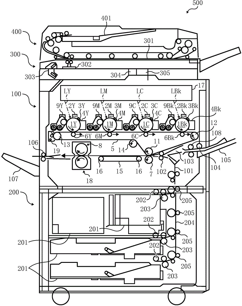
[0029] figure 1 Shown is an overall schematic diagram of a copying machine 500 according to this embodiment.

[0030] The copying machine 500 in this embodiment is a so-called tandem image forming apparatus, and employs a dry two-component developing method using a dry two-component developer. The copier 500 is composed of a copier body 100 , a paper feed table 200 on which the copier body 100 is placed, a scanner 300 mounted on the copier body 100 , and an automatic document feeder 400 mounted above the scanner 300 .

[0031] The copier 500 performs image forming processing after receiving image data as image information read by the scanner ...

Example Embodiment

[0115] [Embodiment 2]

[0116] Hereinafter, a second embodiment in which the present invention is applied to an electrophotographic full-color printer serving as an image forming apparatus will be described with reference to the drawings. In addition, since the basic configuration of the copier 500 of this embodiment is the same as that of the copier 500 of Embodiment 1, description thereof will be omitted.

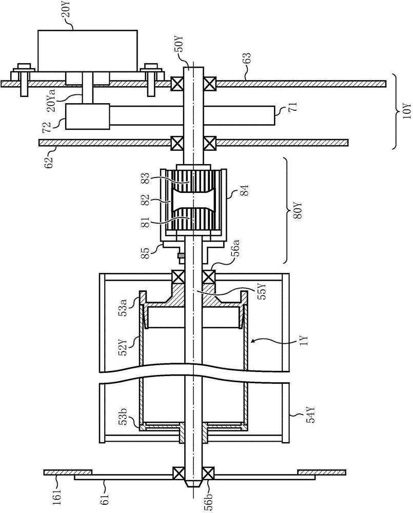
[0117] Figure 12 Shown is a cross-sectional view of a schematic configuration of a photoreceptor driving device according to Embodiment 2. FIG. exist Figure 12 In this case, since the photoreceptor drum unit 54Y and the photoreceptor driving section 10Y are constituted the same as those in Embodiment 1 Figure 12 The illustrated photoreceptor driving device is the same, so its description is omitted.

[0118] exist Figure 12 In the photoreceptor driving device of the present embodiment shown, as the two-stage coupling part 80Y connecting the photoreceptor drum uni...


PUM

PropertyMeasurementUnit
Outer diameteraaaaaaaaaa
Tooth widthaaaaaaaaaa

Abstract

A power transmission device includes a drive coupling, a driven coupling, and an intermediate transmission member. The drive coupling receives power from a drive source and rotates. The driven coupling is disposed coaxially on a first rotary shaft of the drive coupling and detachably attachable relative to the main body of the image forming apparatus. The intermediate transmission member meshes with the drive coupling and the driven coupling and is held by one of the drive coupling and the driven coupling in a state in which the driven coupling is disengaged from the main body. One of the drive coupling and the driven coupling, whichever holds the intermediate transmission member, constitutes a retaining coupling including an attachment member attached to one of a drive-side device and a driven-side device, and a stopper assembly facing the intermediate transmission member in an axial direction of the first rotary shaft.

Description

technical field [0001] The present invention relates to a drive transmission device and an image forming device. Background technique [0002] An electrophotographic image forming apparatus includes a rotating body such as a photoreceptor or a developing roller, and drives such a rotating body to form an image. Most of such revolving bodies are configured so as to be detachable from the main body of the image forming apparatus so as to be replaceable. Therefore, the drive transmission mechanism that transmits the drive force from the drive source of the image forming apparatus main body to the rotary body is provided with a coupling that detachably connects both. [0003] Patent Document 1 discloses a drive transmission device having an intermediate transmission part, which arranges the output shaft on the drive source side and the input shaft on the revolving body side on the same axis, and provides a drive source between the two shafts. The internal gear meshes with the ...

Claims


Application Information

Patent Timeline
IPC IPC(8): G03G15/00G03G21/16F16D3/18
CPCF16D11/00G03G15/00G03G15/1615G03G15/757G03G21/1647G03G21/186F16D1/101F16D3/185Y10T74/19642F16D2001/103F16D3/50
Inventor 山崎公晴宫胁胜明渡边哲夫松田裕道
Owner RICOH KK
Why Eureka
Try Eureka