Centrifugal casting machine for manufacturing rotor

A centrifugal casting and rotor technology, used in the manufacture of stator/rotor bodies, etc., can solve the problems of gaps between silicon steel sheets, cumbersome operations, and the pressure cannot be uniformly transmitted to the iron core, and achieve the effect of inhibiting inflow or loss.

Active Publication Date: 2015-03-18
HYUNDAI ELECTRIC & ENERGY SYST CO LTD
View PDF13 Cites 8 Cited by
  • Summary
  • Abstract
  • Description
  • Claims
  • Application Information

AI Technical Summary

Problems solved by technology

[0009] As far as the existing rotor centrifugal casting device is concerned, there is the following problem: when the fixing bolts of the upper mold and the lower mold are fastened and connected, the silicon steel sheet constituting the iron core is passed by the pressure transmitted from the upper mold and the lower mold to the iron core. However, since the space for forming the end ring is formed in the upper mold and the lower mold, the pressure cannot be uniformly transmitted to the iron core, and a gap is partially formed between the silicon steel sheets, and the melt flows into it. When it comes to the gap between the silicon steel sheets, especially when it comes to the upper mold, as the pressure is concentrated to the central part of the iron core through the vent part, the gap frequently occurs on the outer diameter side of the silicon steel sheet
[0010] In addition, when forming rotors with the same diameter but different lengths (heights), it is necessary to replace the fixing device, which has an iron core stacked inside, and the fixing bolts, etc., with other ones. Combined to reconfigure the centrifugal casting device, so there is a problem that the work is very cumbersome
[0011] In addition, after the manufacture of the rotor is completed, in order to take out the rotor in the fixture, it is necessary to separate the upper mold and the lower mold and then use another device or tool to forcibly take out the rotor in the fixture, so there is a problem that it is not easy to take out the product

Method used


Image

  • Centrifugal casting machine for manufacturing rotor
  • Centrifugal casting machine for manufacturing rotor
  • Centrifugal casting machine for manufacturing rotor

Examples


Embodiment Construction

[0026] Hereinafter, preferred embodiments of the present invention will be described in detail in conjunction with the accompanying drawings. In describing the embodiments of the present invention, if it is judged that the detailed description of related known functions or configurations may unnecessarily obscure the gist of the present invention, the detailed description will be omitted.

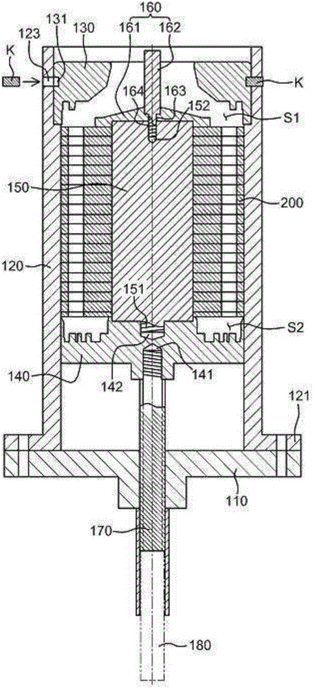
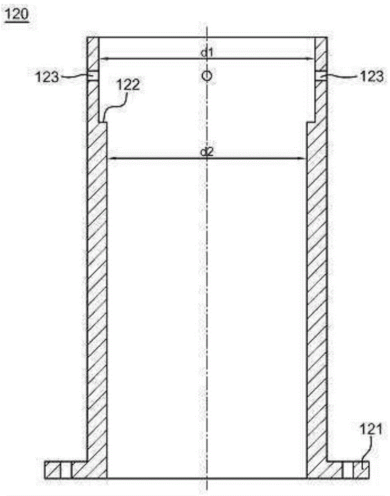
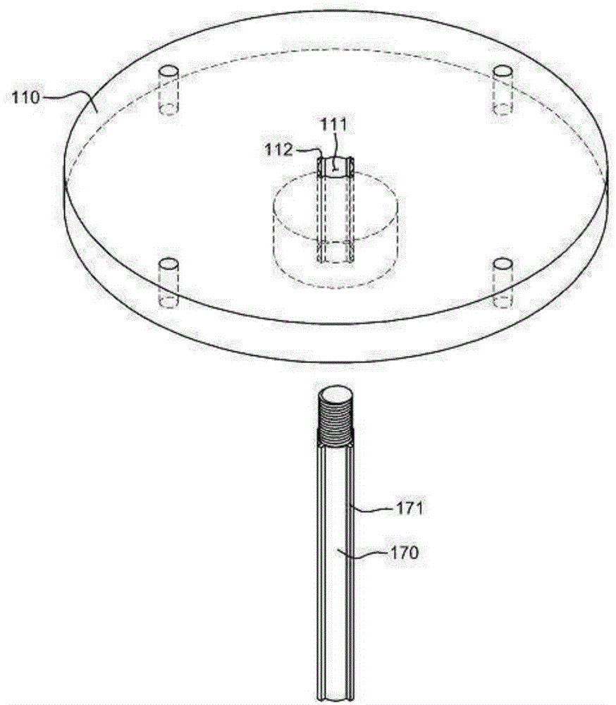
[0027] figure 1 To show a cross-sectional view of the structure of a centrifugal casting device according to a preferred embodiment of the present invention, figure 2 To show a sectional view of the sleeve structure according to the present invention, image 3 It is a perspective view showing the combined structure of the turntable and hydraulic ejector pin according to the present invention.

[0028] The centrifugal casting device according to the present invention has the following characteristics: the lower mold 140 provided at the lower part of the core (core) 200 is configured to mo...


PUM


Abstract

Disclosed herein is a centrifugal casting machine, including: a rotating plate rotating by means of a motor; a cylindrical sleeve installed on the rotating plate and having an internal diameter corresponding to an external diameter of silicon steel plates constituting a core in the sleeve; an upper mold internally installed on the sleeve to define a first molding space into which a molten metal is introduced to mold an end ring; a lower mold internally installed on the sleeve to define a second molding space into which a molten metal is introduced to mold an end ring; a dummy shaft fitted in the center of the core and coupled to the lower mold; a cap coupled to an upper end of the dummy shaft to press the core; and a hydraulic ram coupled to the lower mold to move the lower mold up and down and coupled to the rotating plate to rotate therewith.

Description

technical field [0001] The present invention relates to a centrifugal casting device for manufacturing a rotor used in a rotating machine such as an electric motor or a generator, and more particularly to a centrifugal casting device which is constituted to make it possible that the lower mold is applied with a certain pressure when the rotor is centrifugally cast. Press the iron core (core), so that the silicon steel sheets constituting the iron core are firmly attached to each other, and use the hydraulic ram to move the lower mold up and down, so that the cast product can be easily taken out after the casting operation. Background technique [0002] Generally, a rotating machine such as a motor or a generator is composed of a stator and a rotor as main components, the rotor is arranged at the center of the rotating machine, and the stator is arranged to surround the rotor in the rotating machine and is in a fixed state . [0003] In addition, the rotor is provided with e...

Claims


Application Information

Patent Timeline
Patent Type & Authority Applications(China)
IPC IPC(8): H02K15/02
CPCB22D13/101B22D13/04B22D13/104B22D13/10
Inventor 柳志勋韩广镇李晟模权炳勋金德寿
Owner HYUNDAI ELECTRIC & ENERGY SYST CO LTD
Why Eureka
Try Eureka