Cooling structure of circular-core compressor

A cooling structure and compressor technology, which is applied in the field of center compressors, can solve problems such as unstable movement, explosion, and damage to the compression part of the compressor, and achieve the effect of preventing unstable operation and abnormal explosion

Inactive Publication Date: 2003-12-17
LG ELECTRONICS (TIANJIN) APPLIANCES CO LTD
View PDF0 Cites 7 Cited by
  • Summary
  • Abstract
  • Description
  • Claims
  • Application Information

AI Technical Summary

Problems solved by technology

[0011] The compressor is because the refrigerant passing through the evaporator 40 directly enters the compression chambers C1 and C2. If the refrigerant in the liquid state that has not evaporated in the evaporator 40 enters the compression chambers C1 and C2, the operation will be unstable or an explosion phenomenon will occur. The compression part of the machine produces a lot of damage

Method used


Image

  • Cooling structure of circular-core compressor
  • Cooling structure of circular-core compressor
  • Cooling structure of circular-core compressor

Examples


Embodiment Construction

[0020] How to realize the cooling structure of the circular compressor of the present invention will be further described below in conjunction with the accompanying drawings.

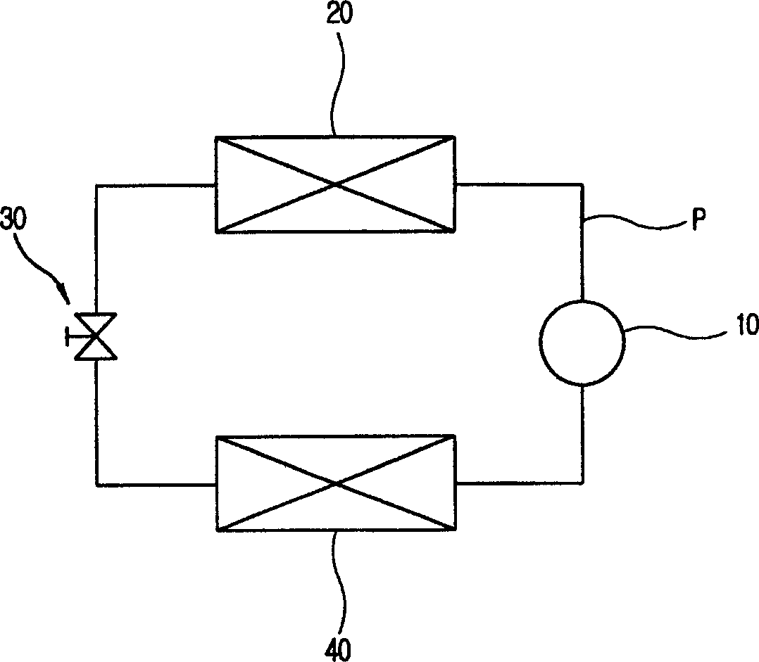
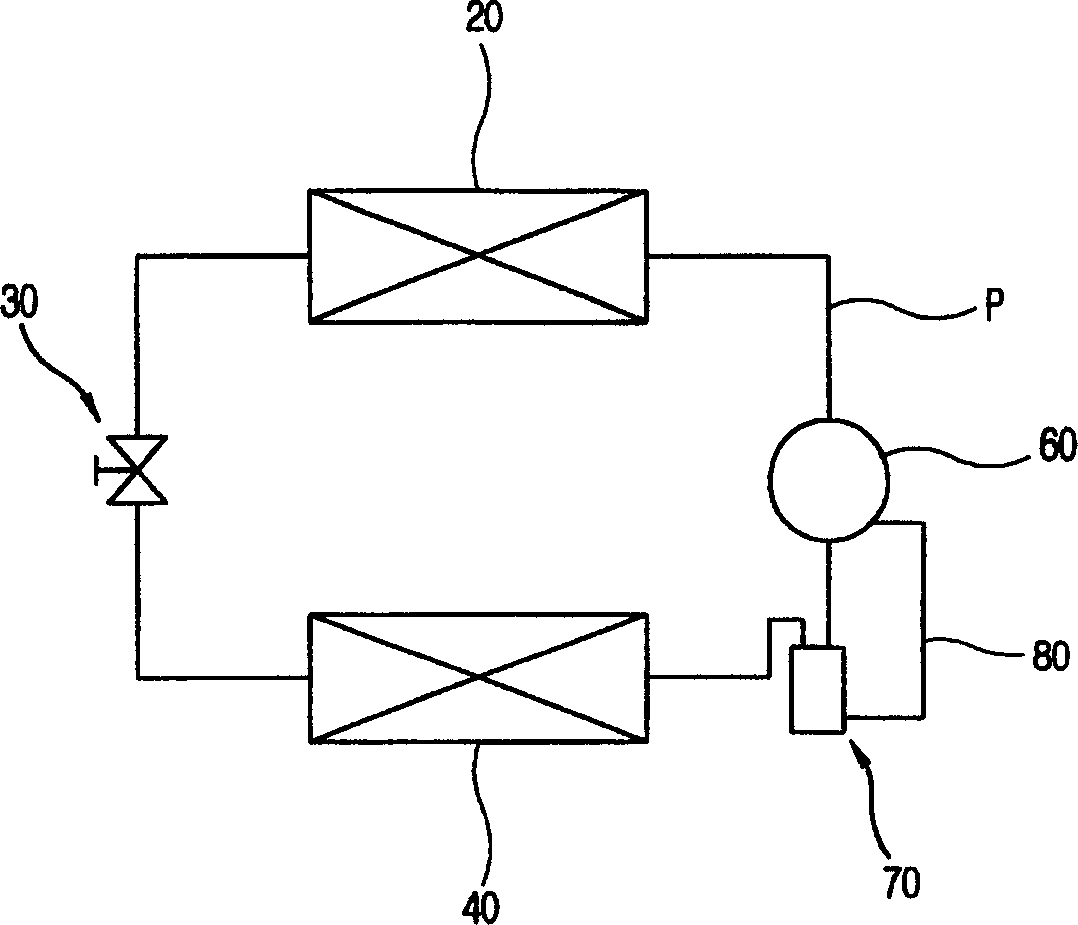
[0021] Such as image 3 As shown, the refrigeration cycle system device is that the compressor 60 is connected to the condenser 20 through the refrigerant pipe P, the condenser 20 is connected to the expansion part 30, the expansion part 30 is connected to the evaporator 40, and the evaporator 40 is connected to the condenser through the refrigerant pipe P. The center compressor 60 is connected. A liquid storage tank 70 for separating liquid-state refrigerant from the refrigerant entering the compressor 60 through the evaporator 40 is coupled to the refrigerant pipe P connecting the evaporator 40 and the compressor.

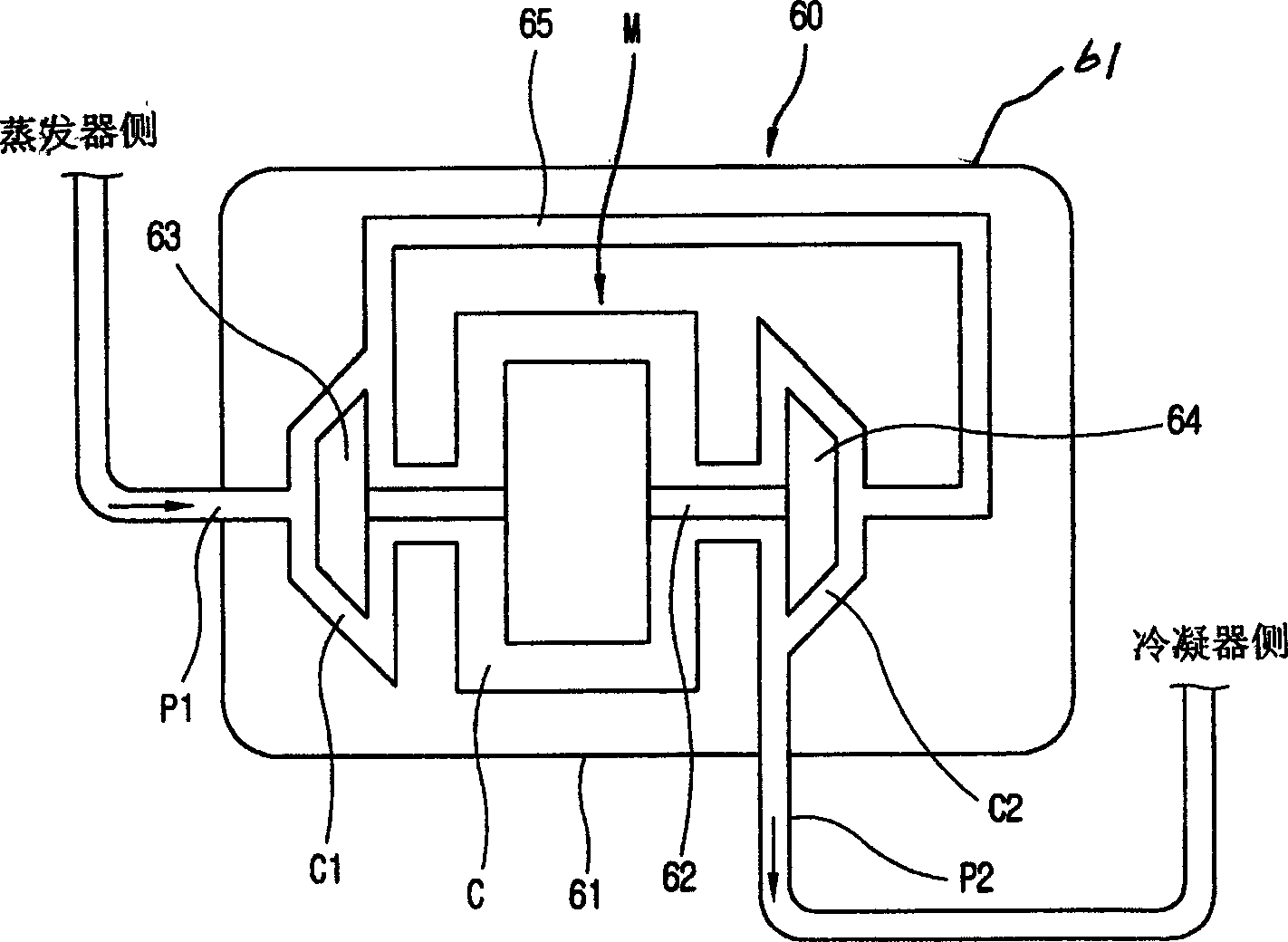
[0022] Such as Figure 4 As shown, there is a motor chamber C in which a motor M is installed in the middle of the airtight container 61 that forms a certain inner space on the circular ...


PUM


Abstract

A cooling structure of circular-core compressor is disclosed. In the freeze circulating system, the evaporator communicated via cold medium tube to the circular-core compressor is used to separate the liquid cold medium from gas cold medium, and a liquid cold medium tube is used to suck the gas cold medium into the liquid accumulator of compressing chamber and to guide the liquid cold medium collected on said liquid accumulator to the high-temp part of compressor. It can prevent the liquid cold medium from flowing in to cause explosion and uniformly cool the high-temp part of compression.

Description

technical field [0001] The present invention relates to an invention of a circular compressor, in particular a circular compressor that smoothly cools the heat generated by the circular compressor constituting a refrigeration cycle system during high-speed rotation, and prevents the inflow of liquid refrigerant. cooling structure. Background technique [0002] Generally, the refrigerating cycle system installed on a refrigerating and air-conditioning device such as a refrigerator or an air conditioner, such as figure 1 As shown, the compressor 10 is connected to the condenser 20 through the refrigerant pipe P, the condenser 20 is connected to the expansion part 30, the expansion part 30 is connected to the evaporator 40, and the evaporator 40 is connected to the compressor 10 through the refrigerant pipe P to form a closed circulatory system. [0003] In the refrigeration cycle system as described above, power is applied to the compressor 10, and the compressor 10 starts t...

Claims


Application Information

Patent Timeline
Patent Type & Authority Applications(China)
IPC IPC(8): F04D29/58
Inventor 崔文暢徐光河金永宽智裕喆王大星金會善
Owner LG ELECTRONICS (TIANJIN) APPLIANCES CO LTD
Why Eureka
Try Eureka