Lens capable of changing shooting direction, and operating method thereof
A technology of shooting direction and lens, applied in the field of lens, can solve the problems of increasing the risk of product failure, difficult to take pictures, and inconvenient to take pictures, so as to reduce the risk of product failure, save the cost of production materials, and achieve the effect of simple and convenient operation.
- Summary
- Abstract
- Description
- Claims
- Application Information
AI Technical Summary
Problems solved by technology
Method used
Image
Examples
Embodiment 1
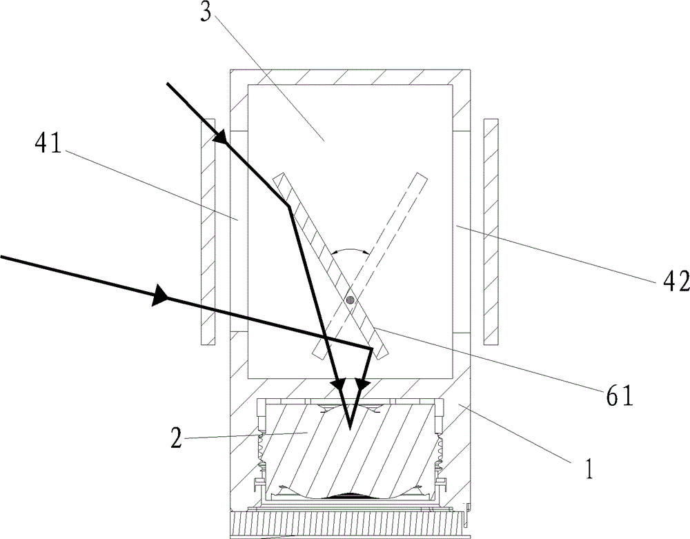
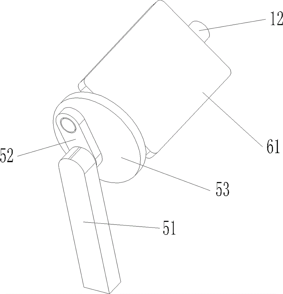
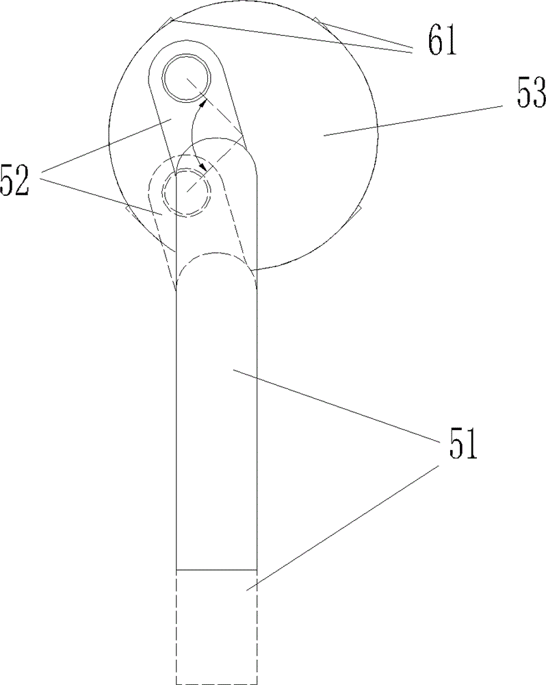
[0044] like figure 1 and figure 2 As shown, a lens capable of changing the shooting direction includes a lens assembly mounting seat 1 and an optical lens assembly 2 installed in the lens assembly mounting seat, and a light guide cavity is arranged in front of the optical lens assembly in the lens assembly mounting seat 3. The light guide cavity extends in different directions to form the first light guide groove and the second light guide groove. The end of the first light guide groove is provided with a first light hole 41, and the end of the second light guide groove is provided with a second light guide groove. The light through hole 42, the opening direction of the first light through hole 41 and the second light through hole 42 are opposite;
[0045] The lens capable of changing the shooting direction also includes a light guide switching device, the light guide switching device includes a driving assembly and a light guide driven by the driving assembly, the light guide...
Embodiment 2
[0050] like image 3 , Figure 4 and Figure 5 As shown, different from Embodiment 1, Embodiment 2 is also provided with concave lenses 7 at the first light through hole and the second light through hole, respectively, on the optical path between the reflective plane mirror and the optical lens assembly as the light guide. A convex lens 8 is also provided.
[0051] By using a concave lens, it is possible to capture more pictures outside the light hole when the area of the light hole is constant; the use of a convex lens is conducive to reducing the area of the photosensitive chip of the handheld mobile device and reducing the production cost of the product.
Embodiment 3
[0053] like Figure 6 , Figure 7 , Figure 8 and Figure 9 As shown, the difference from the second embodiment is that the light guide member of the third embodiment is provided with a corresponding first reflective surface 91 and a second reflective surface 92, and a radial through groove 10 is provided on the side wall of the light guide cavity. The light guide is connected to the drive assembly through a connecting rod 11 installed in the radial through groove, the light guide can be a "V" shaped reflector 62, the first reflective surface 91 and the second reflective surface 92 Located at the bottom of the "V" shaped reflector 63, the drive assembly includes a second coil motor and a second drive rod 54 driven by the second coil motor to reciprocate, and the connecting rod 11 is connected to the second drive rod 54 .
PUM
 Abstract
Description
Claims
Application Information
 - R&D
- Intellectual Property
- Life Sciences
- Materials
- Tech Scout
- Unparalleled Data Quality
- Higher Quality Content
- 60% Fewer Hallucinations
Browse by: Latest US Patents, China's latest patents, Technical Efficacy Thesaurus, Application Domain, Technology Topic, Popular Technical Reports.
© 2025 PatSnap. All rights reserved.Legal|Privacy policy|Modern Slavery Act Transparency Statement|Sitemap|About US| Contact US: help@patsnap.com


