
Rotating device for binding system

A technology of rotating device and rotating ring, which is applied in the field of garden and forestry machinery to achieve the effects of high work efficiency, uniform wrapping of straw rope and simple structure

Inactive Publication Date: 2015-03-25
芜湖赛德交通设备有限公司
View PDF8 Cites 9 Cited by
  • Summary
  • Abstract
  • Description
  • Claims
  • Application Information

AI Technical Summary

Problems solved by technology

[0004] In order to solve the above-mentioned problems in the prior art, the present invention aims to provide a rotating device for a binding system which has the advantages of simple structure, low cost, easy operation, low labor intensity, high work efficiency, and uniform wrapping of straw ropes. Realize the function of quickly wrapping the straw rope on the trunk, solve the defects of the manual operation of the existing sanitation workers, and save a lot of human resources

Method used


Image

  • Rotating device for binding system
  • Rotating device for binding system
  • Rotating device for binding system

Examples


Embodiment Construction

[0013] In order to make the technical means, creative features, goals and effects achieved by the present invention easy to understand, the present invention will be further described below in conjunction with specific illustrations.

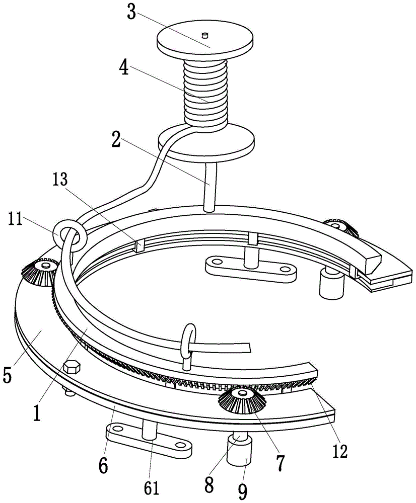
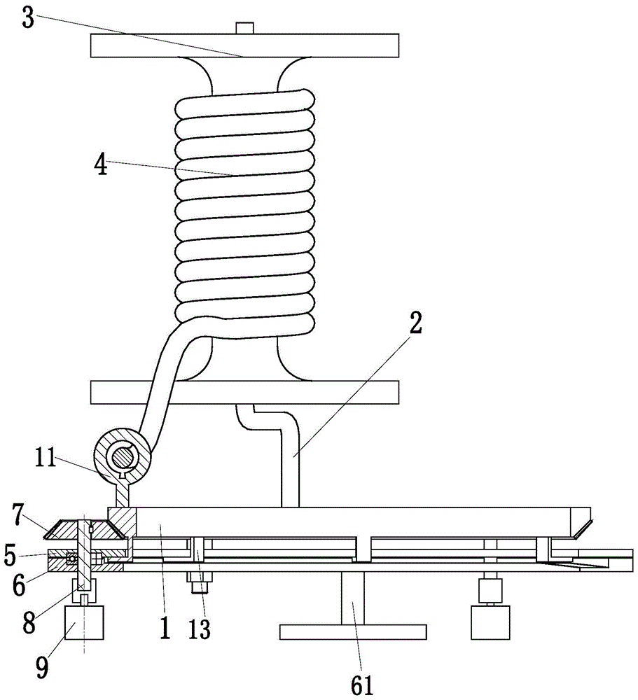
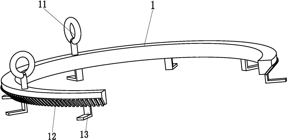
[0014] Such as Figure 1 to Figure 4 As shown, a rotating device for a binding system includes a rotating ring 1, a mounting rod 2, a pulley 3, a grass rope 4, an upper fixing ring 5, a lower fixing ring 6, three transmission bevel gears 7, three transmission shafts 8 and three A transmission motor 9, the right side of the rotating ring 1, the upper fixing ring 5 and the lower fixing ring 6 are all provided with openings, the angle of the opening is 90 degrees with respect to the central axis of the rotating ring 1, and the opening is used as the entrance of the trunk. Sanitation workers operate the trunk to enter and stay in the center of the rotating ring 1 from the opening; two rope-through rings 11 are arranged on the rear side of the upper ...


PUM


Abstract

The invention relates to a rotating device for a binding system. The rotating device for the binding system comprises a rotating ring, a mounting rod, a pulley, a straw rope, an upper fixing ring, a lower fixing ring, three drive bevel gears, three drive shafts and three drive motors. Two rope through rings are arranged on the rear side of the upper end face of the rotating ring, an outer bevel gear is arranged at the lower end of the outer wall of the rotating ring, and six L-shaped positioning rods are symmetrically arranged at the lower end of the rotating ring. The mounting rod is welded to the front side of the upper end face of the rotating ring. The pulley and the mounting rod are connected through a bearing. The straw rope is arranged on the pulley in a sleeving mode, and the straw rope sequentially penetrates through the two rope through rings on the rotating ring. The six L-shaped positioning rods of the rotating ring are placed between the stepped face of the lower fixing ring and the lower end face of the upper fixing ring. The rotating device for the binding system has the advantages of being simple in structure, low in construction cost, easy and convenient to operate, low in labor intensity, high in working efficiency, even in straw rope wrapping and the like, and the straw rope wrapping function can be quickly and evenly achieved.

Description

technical field [0001] The invention relates to the technical field of garden and forestry machinery, in particular to a rotating device for a binding system. Background technique [0002] In the cold winter, on both sides of the street, you can see that sanitation workers will take measures such as wrapping straw ropes on the trunks of greening trees. The purpose of wrapping straw ropes on the trunks is: 1. It can keep warm for the winter of the tree species that are not resistant to freezing Work; 2. It has the function of moisturizing the trunk, and can keep the grass rope moist through rainfall or artificial watering, thereby improving the survival rate of trees; 3. The grass rope also has the function of blocking sunlight and preventing bark burns. [0003] However, the above-mentioned measures such as wrapping the trunks with straw ropes are all done manually by sanitation workers. Due to the continuous acceleration of the pace of modern cities, the city has higher and...

Claims


Application Information

Patent Timeline
Patent Type & Authority Applications(China)
IPC IPC(8): A01G13/02
CPCA01G13/025A01G13/0225
Inventor 刘俊
Owner 芜湖赛德交通设备有限公司
Learn More