Ventricular drainage tube pressure control device

A technology for ventricle drainage and control device, which can be used in suction devices, hypodermic injection devices, etc., and can solve problems such as inconvenience for medical staff

Inactive Publication Date: 2017-05-10
陈高科
View PDF18 Cites 1 Cited by
  • Summary
  • Abstract
  • Description
  • Claims
  • Application Information

AI Technical Summary

Problems solved by technology

[0003] This patent is different from the technical solution of the above-mentioned patent. When the above-mentioned patent is in use, it is necessary to limit the height of the drainage bottle or the discharge end of the ventricle drainage tube so that the liquid in the ventricle drainage tube can give a certain pressure to the ventricle. The position needs to be adjusted, so it brings great inconvenience to the medical staff

Method used


Image

  • Ventricular drainage tube pressure control device

Examples


Embodiment Construction

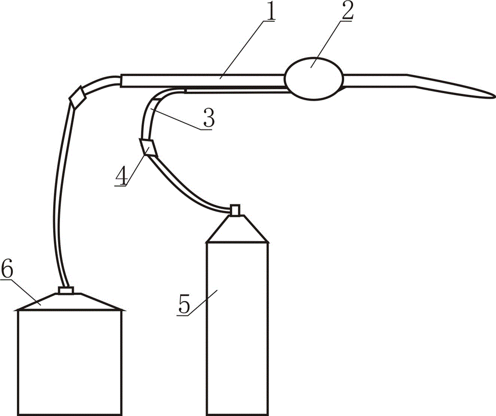
[0013] Such as figure 1 As shown, the ventricular drainage tube pressure control device includes a ventricular drainage tube 1, a pressure balloon 2, an airway tube 3, an inflation joint 4 and a high-pressure air source 5, and the inflation joint 4 is a conical structure. The ventricular drainage tube 1 passes through the pressure balloon 2 , one end of the airway tube 3 is connected to the pressure balloon 2 , and the other end is connected to the inflation connector 4 , and the inflation connector 4 is connected to the high-pressure gas source 5 .

[0014] A liquid container 6 is connected to the liquid discharge end of the ventricular drainage tube 1 .

[0015] When in use, the high-pressure air source inflates the pressure air bag through the inflatable joint and the air guide tube, thereby flattening the pipeline of the ventricle drainage tube 1, so that the ventricle drainage tube 1 maintains a certain pressure. The liquid discharge end can be placed arbitrarily, and th...


PUM


Abstract

The invention discloses a pressure control device for a ventricle drainage tube, which comprises a ventricle drainage tube, a pressure air bag, an air guide tube, an inflatable joint and a high-pressure air source. The ventricle drainage tube passes through the pressure air bag, and one end of the air guide tube is connected to The pressure air bag is connected, the other end is connected with the inflation joint, and the inflation joint is connected with the high-pressure air source. A liquid container is connected to the liquid discharge end of the ventricle drainage tube. The inflation joint is a conical structure. Due to the above-mentioned structure, the pressure air bag flattens the pipeline of the ventricle drainage tube to maintain a certain pressure in the ventricle drainage tube. The height of the liquid discharge end is limited, which brings great convenience to medical staff.

Description

technical field [0001] The invention relates to the technical field of medical devices, in particular to a pressure control device for a ventricular drainage tube. Background technique [0002] On June 25, 2014, the State Intellectual Property Office published a patent document with a publication number of CN203663140U and a patent name of a neurosurgical ventricular drainage device. The neurosurgical ventricular drainage device includes a ventricular drainage tube connected to Drainage bottle, there is a three-way valve between the ventricle drainage tube and the drainage bottle, the three-way valve is equipped with a three-way switch, and the connecting tube at the other end of the drainage bottle is connected with the drainage bag, and it is characterized in that: the upper end of the three-way valve is open With heparin cap. The structure is simple and easy to use; the top of the heparin cap is equipped with a rubber pad, which can be repeatedly punctured and injected, ...

Claims


Application Information

Patent Timeline
Patent Type & Authority Patents(China)
IPC IPC(8): A61M1/00
CPCA61M1/743
Inventor 陈高科
Owner 陈高科
Why Eureka
Try Eureka