Die holder device capable of sliding

A mold base and sliding plate technology, applied in metal processing equipment, forming tools, manufacturing tools, etc., can solve the problems of the discount of forming efficiency, the forming speed of hydraulic presses is not as good as that of mechanical presses, etc., to achieve convenient removal, improve production efficiency, ensure The effect of stamping accuracy

Active Publication Date: 2015-03-25
泰州浙华机械精锻有限公司
View PDF8 Cites 7 Cited by
  • Summary
  • Abstract
  • Description
  • Claims
  • Application Information

AI Technical Summary

Problems solved by technology

[0002] All kinds of existing cold or hot forming presses are composed of fuselage, frame, slider for fixing the upper mold and base for fixing the lower mold, etc., especially for some domestic mechanical presses, the largest slider The stroke is generally below 400mm.

Method used


Image

  • Die holder device capable of sliding

Examples


Embodiment 1

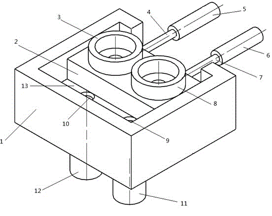
[0023] Such as figure 1 As shown, the present invention adopts a technical solution as a slidable lower mold base device, which includes a cuboid-shaped lower mold base 1. The upper center of the lower mold base 1 is provided with a rectangular parallelepiped groove 13, and the rectangular parallelepiped groove 13 is provided with A sliding plate 2 sliding left and right in it. The surface of the sliding plate 2 is provided with a first mold jacket 3 and a second mold jacket 8 arranged side by side. The first mold jacket 3 and the second mold jacket 8 are equipped with stamping dies. ;

[0024] The right side of the rectangular parallelepiped groove 13 is provided with a notch, and the right side of the lower mold base 1 is provided with a first driving mechanism 5 and a second driving mechanism 6 arranged side by side in front and rear, the first driving mechanism 5 and the second driving mechanism 6 is arranged horizontally, the first driving mechanism 5 and the second driving ...


PUM


Abstract

The invention discloses a die holder device capable of sliding. The die holder device includes a cuboid die holder. A cuboid groove is formed in the center of the upper portion of the die holder. A sliding plate which slides left and right in the cuboid groove is arranged in the cuboid groove. A first outer die sleeve and a second outer die sleeve are arranged in parallel in the front-back direction on the surface of the sliding plate. Punching dies are placed in the first outer die sleeve and the second outer die sleeve. A notch is formed in the right side face of the cuboid groove. A first drive mechanism and a second drive mechanism are arranged in parallel in the front-back direction on the right side face of the die holder. Two vertical through holes are formed in parallel in the front-back direction in the bottom surface of the left of the die holder, and a first ejector beam and a second ejector beam are arranged in the two through holes respectively. According to the die holder device, the sliding plate provided with multi-station dies is moved out of the position underneath a slide block through an air cylinder so that the working procedures of feeding and discharging can be performed; meanwhile, a hydraulic cylinder ejecting device is arranged underneath the die holder; accordingly, quick, safe and efficient punching production can be achieved.

Description

technical field [0001] The invention relates to a mold equipment for metal stamping, in particular to a slidable lower mold base device. Background technique [0002] All kinds of existing cold or hot forming presses are composed of fuselage, frame, slider for fixing the upper mold and base for fixing the lower mold, etc., especially for some domestic mechanical presses, the largest slider The stroke is generally below 400mm. For the processing of hollow long-axis parts, due to the limitation of the stroke of the slider, hydraulic presses are used for forming. The forming speed of hydraulic presses is far lower than that of mechanical presses, so the forming efficiency is greatly reduced. The invention provides a lower mold base structure with a sliding plate. The sliding plate equipped with a multi-station mold is moved out from the bottom of the slider by the cylinder to perform the loading and unloading process. At the same time, a hydraulic cylinder jacking device is pro...

Claims


Application Information

Patent Timeline
IPC IPC(8): B21D37/04B21D45/02
CPCB21D37/04B21D45/02
Inventor 张学华张伟杨奕聪孔祥志
Owner 泰州浙华机械精锻有限公司
Why Eureka
Try Eureka