
Welding method of lower vehicle body

A welding method and automobile technology, applied in welding equipment, vehicle parts, transportation and packaging, etc., can solve problems such as excessive loading time, inability to complete grasping, gluing and placing, and increasing long-term production and operation costs. Achieve the effect of reducing complexity and ensuring the quality of body products

Inactive Publication Date: 2015-03-25
BEIQI FOTON MOTOR CO LTD
View PDF5 Cites 5 Cited by
  • Summary
  • Abstract
  • Description
  • Claims
  • Application Information

AI Technical Summary

Problems solved by technology

[0007] The biggest disadvantage of the existing technology is that the tack welding station as the sub-assembly of the lower body cannot achieve enough tack welding spot welding. The most fundamental reason for this phenomenon is that there is too much loading time in a working cycle
[0008] Under the condition of multi-model collinear production, since there is only one position space for the assembly fixture, in order to meet the positioning of multiple models, it is necessary to switch some fixture units, which leads to the complexity of the fixture and also leads to an increase in failures
[0009] Due to the large amount of glue applied to the left front longitudinal beam assembly, the right front longitudinal beam assembly and the front floor assembly, a single robot cannot complete the single-cycle process of grasping, gluing and placing parts within a fixed cycle, so manual Apply glue to the left front side beam assembly and right front side beam assembly (additional equipment will not be analyzed), which increases the risk of glue quality degradation
There are many operators, which increases the long-term production and operation costs

Method used


Image

  • Welding method of lower vehicle body

Examples


Embodiment Construction

[0021] Embodiments of the present invention are described in detail below, examples of which are shown in the drawings, wherein the same or similar reference numerals designate the same or similar elements or elements having the same or similar functions throughout. The embodiments described below by referring to the figures are exemplary and are intended to explain the present invention and should not be construed as limiting the present invention.

[0022] In describing the present invention, it should be understood that the terms "center", "longitudinal", "transverse", "length", "width", "thickness", "upper", "lower", "front", " Orientation or position indicated by "back", "left", "right", "vertical", "horizontal", "top", "bottom", "inner", "outer", "clockwise", "counterclockwise", etc. The relationship is based on the orientation or positional relationship shown in the drawings, and is only for the convenience of describing the present invention and simplifying the descrip...


PUM


Abstract

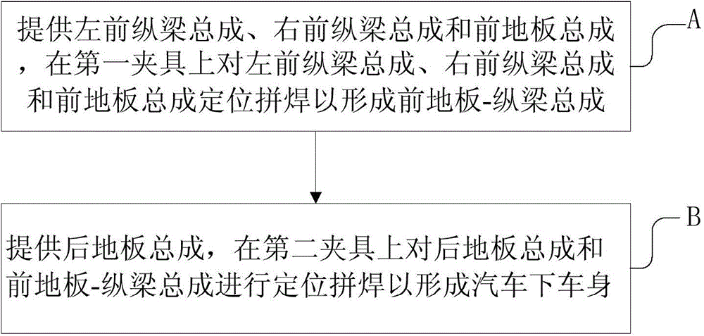
The invention discloses a welding method of a lower vehicle body. The welding method comprises the following steps: (A) a left front longitudinal beam assembly, a right front longitudinal beam assembly and a front floor assembly are provided; and the positioned welding is performed for the left front longitudinal beam assembly, the right front longitudinal beam assembly and the front floor assembly on a first fixture to form a front floor-longitudinal beam assembly; and (B) a back floor assembly is provided; and the positioned welding is performed for the back floor assembly and the front floor-longitudinal beam assembly on a second fixture to form the lower vehicle body. According to the welding method of the lower vehicle body, through the two-fixture positioned welding mode, the complexity of the fixtures for collinear production of multiple vehicle types is effectively reduced, the process and equipment complexity is reduced, and a certain effect on the vehicle body product quality is achieved.

Description

technical field [0001] The invention relates to the technical field of automobile manufacturing, in particular to a welding method for an automobile lower body. Background technique [0002] In view of the continuous improvement of automobile production capacity, it is very important to increase the tempo of automobile body welding; at the same time, due to the variety of vehicle body platforms, in order to reduce manufacturing costs, the body welding equipment must be flexible, especially the positioning of the lower body welding equipment. [0003] Generally, the sub-assembly of the lower body is tailor-welded from the left front longitudinal beam assembly, the right front longitudinal beam assembly, the front floor assembly and the rear floor assembly, so the manual operation of this kind of welding deviates from the development of the automobile industry. At the same time, the welding quality of the sub-assembly of the lower body cannot be guaranteed to be stable and un...

Claims


Application Information

Patent Timeline
IPC IPC(8): B23K31/02
CPCB23K31/02B23K2101/006
Inventor 王明正
Owner BEIQI FOTON MOTOR CO LTD
Learn More