Spreading machine

A spreader and frame technology, which is applied in the directions of spreading thin soft materials, thin material handling, transportation and packaging, etc., can solve the problems of inability to arrange the device to spread cloth, unable to apply cloth, and unable to convey cloth in a predetermined direction, etc.

Active Publication Date: 2015-08-05
石狮市卓诚机械自动化设备有限责任公司
View PDF6 Cites 2 Cited by
  • Summary
  • Abstract
  • Description
  • Claims
  • Application Information

AI Technical Summary

Problems solved by technology

[0005] 1. The cloth feeding device and cloth spreading device of the existing cloth spreading machine are respectively driven by independent motors, so it is difficult to achieve synchronous operation of the two running speeds; if the running speed of the cloth feeding device is higher than that of the spreading device, That is, there is a phenomenon of cloth stacking between the two devices; if the running speed of the cloth feeding device is lower than that of the spreading device, there will be a phenomenon of cloth pulling between the two devices; whether there is a phenomenon of cloth stacking or pulling is not conducive to spreading The device performs the spreading action, which cannot effectively flatten the folds of the fabric, which affects the cutting and splicing of the fabric in the later stage
[0006] 2. The cloth spreading device of the existing cloth spreading machine flattens the cloth through the rolling cloth rollers on the frame that roll against each other, and then enters the cloth arrangement device after being clamped and drawn out; During the spreading action, the fabric is relatively uneven, and wrinkles often appear. In the later stage of cutting, due to the influence of wrinkles, the edge of the cut fabric is not smooth, and when the fabric is spliced, the pattern, etc. cannot be aligned. ; and the cloth pressing rollers that roll against each other are fixedly set, the cloth head is not easy to pass through the gap between the two pressing rollers, and because the two pressing rollers are fixed and cannot be adjusted, it cannot be applied to cloth of different thicknesses, and the practicability is relatively poor
[0007] 3. When the cloth spreading device of the existing cloth spreading machine is relatively smooth, the cloth friction force is small and it is easy to flutter. When the cloth spreading is completed, the cloth cannot be conveyed in the predetermined direction, and wrinkles appear again when the cloth is spread. Relatively uneven, affecting spreading efficiency
[0008] 4. When the existing cloth spreader puts the cloth to the cloth distribution device, because the cloth feeding roller is in the rotating state, the cloth may be wound on the cloth feeding roller, and the cloth cannot be conveyed in the predetermined direction, and the cloth cannot be arranged smoothly. The device spreads the cloth, which affects the spreading efficiency
[0009] 5. Existing spreaders are generally located in large workshops, where the wind is relatively strong. During the conveying process of the cloth after spreading, it will be blown and swelled by the wind, making the cloth unable to be conveyed smoothly and affecting the spreading efficiency.
[0010] 6. When the existing fabric spreader spreads the fabric back and forth, the two ends of the fabric cannot be folded and pressed because of the characteristics of the fabric, and the folded part of the fabric is easy to bulge, and the fabric will slide, making the laid fabric uneven. During post-cutting, due to the influence of uneven fabric, the edge of the cut fabric is not smooth
However, in the one-way spreading method, each layer of fabric needs to clamp the fabric section to the beginning of the spread, and then lay the fabric to the end of the required cut spread, and repeat the operation until the spread is complete; Originally, it was wound on the fabric roll, so the section of the fabric will generally bulge up or down, and the fabric will slide, making the laid fabric uneven. When cutting, due to the influence of the uneven fabric, The edge of the cut fabric is not smooth, and the spreading efficiency is poor

Method used


Image

  • Spreading machine
  • Spreading machine
  • Spreading machine

Examples


Embodiment Construction

[0096] In order to further explain the technical solution of the present invention, the present invention will be described in detail below through specific examples.

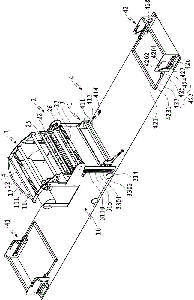
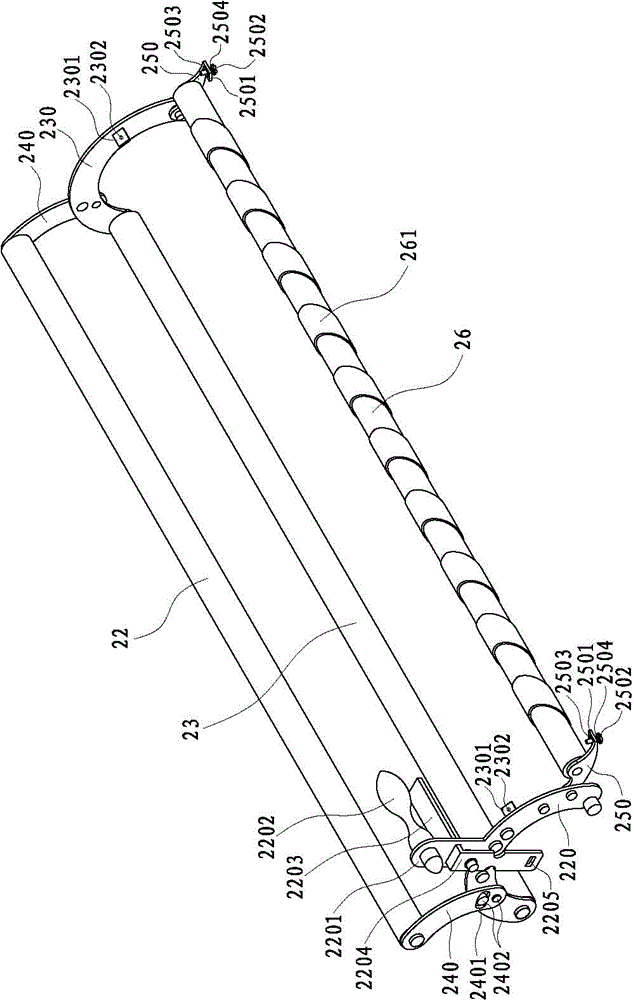
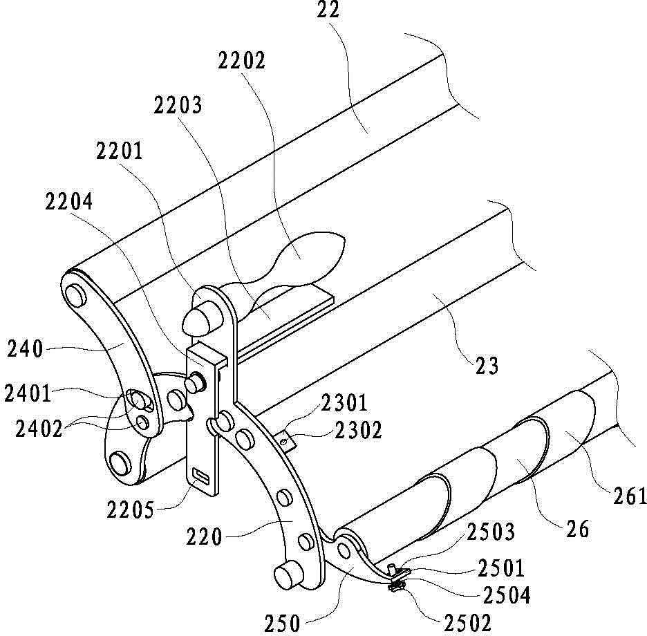
[0097] see Figure 1 to Figure 27 , the present invention discloses a spreading machine, which includes a frame and a cloth feeding device 1, a spreading device 2 and a spreading device 4 arranged on the frame;

[0098] The cloth feed device 1 includes a first cloth guide roller 11, a first cloth feed roller 12, a tension roller 13 and a first cloth outlet roller 14, and the first cloth guide roller 11, the first cloth feed roller 12 and the first cloth feed roller 14 A cloth outlet roller 14 is arranged parallel to and sequentially on the frame 10, the first cloth feed roller 12 is driven to rotate by a motor 15, and both ends of the tension roller 13 are pivotally connected to the first cloth outlet roller through the pivot arm 31 14 at both ends; the corresponding cloth passes through the first cloth guide ...


PUM


Abstract

The invention discloses a cloth spreading machine, which comprises a frame, a cloth feeding device, a cloth spreading device and a cloth arranging device arranged on the frame, and the cloth spreading device includes movable cloth pressing rollers arranged parallel to the frame, The cloth releasing roller and two sets of spreading transmission mechanisms with opposite running directions; the movable press roller is located on the path of the cloth from the cloth feeding device to the cloth releasing roller; the spreading transmission mechanism is set on a platform of the frame, located On the path of the cloth from the movable cloth pressing roller to the cloth releasing roller, each cloth spreading transmission mechanism includes a driving wheel, a driven wheel, a second belt and a transmission motor that drives the driving wheel to rotate; with the above structure, the spreading machine of the present invention High spreading efficiency and good spreading effect.

Description

technical field [0001] The invention relates to a spreading machine, in particular to a spreading machine with good spreading effect. Background technique [0002] As an important cloth spreading and stacking tool in the textile industry, the cloth spreading machine saves a lot of manpower for the textile industry; the cloth spreading machine mainly lays the rolled cloth on the machine table, and then uses other machines to cut the flat cloth and then processing. [0003] The cloth spreading machine mainly includes a cloth feeding cradle device for placing the cloth roll, a cloth feeding device for transporting the cloth, a cloth spreading device for spreading the cloth, and a cloth arrangement device for laying and folding the cloth; the existing cloth spreading machine rotates and releases the cloth through the cloth feeding cradle device. , the cloth is pulled to the cloth spreading device through the cloth feeding device, which is beneficial to the mutual rolling press ...

Claims


Application Information

Patent Timeline
Patent Type & Authority Patents(China)
IPC IPC(8): B65H47/00
Inventor 蔡忠溪
Owner 石狮市卓诚机械自动化设备有限责任公司
Why Eureka
Try Eureka