Clamp for plate

A fixture and plate technology, applied in the field of fixtures, can solve problems such as plate damage and small force-bearing surface

Inactive Publication Date: 2015-03-25
常州市瑞鸿达工具有限公司
View PDF0 Cites 9 Cited by
  • Summary
  • Abstract
  • Description
  • Claims
  • Application Information

AI Technical Summary

Problems solved by technology

[0002] For the handling and loading of large panels, it is difficult to carry out by manpower, especially in places where the space is rela...

Method used


Image

  • Clamp for plate
  • Clamp for plate

Examples


Embodiment Construction

[0012] The present invention will be further described below in conjunction with the accompanying drawings and specific embodiments.

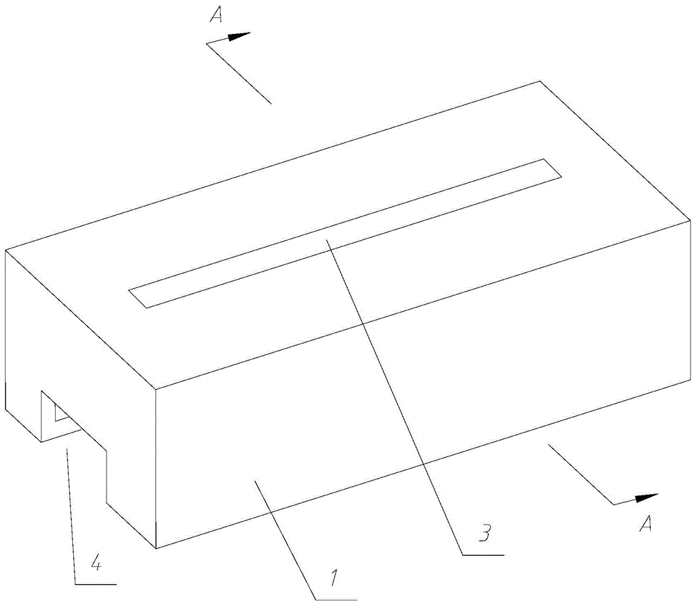
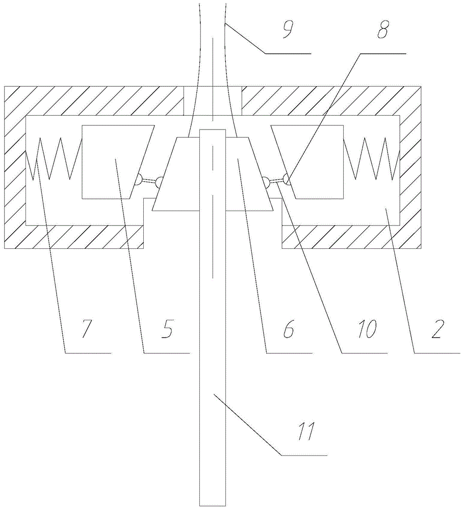
[0013] Such as figure 1 , 2 , a clamp for a plate, including a square prism-shaped housing 1, the housing has a square prism-shaped cavity 2, the upper end surface of the housing is provided with an upper through hole 3 arranged longitudinally, and the lower end surface is provided with There is a lower through hole 4 arranged longitudinally, and a pair of pressing blocks 5 with a right-angled trapezoidal cross-section and a pair of clamping blocks 6 with a right-angled trapezoidal cross-section are arranged inside the housing. The walls are connected by a spring 7, and the surfaces of the oblique waists of the pressing block and the clamping block are provided with a number of roller grooves parallel to the oblique waists, and paired rollers 8 are arranged in the roller grooves. The rollers of the rollers are connected by roller shafts, and ...


PUM


Abstract

The invention relates to a clamp for a plate. The clamp comprises a shell in the shape of a square prism, wherein a cavity in the shape of the square prism is formed in the shell; an upper through hole and a lower through hole are longitudinally formed in the upper end surface and the lower end surface of the shell; a pair of pressure blocks and a pair of clamping blocks of which sections are in the shapes of right trapezoids are arranged in the shell; the plane on which the right-angled waists of the pressure blocks are located and the inner side wall of the shell are connected by virtue of a spring; a plurality of roller slots parallel to the inclined waists are arranged on the planes on which the inclined waists of the pressure blocks and the clamping blocks are located; rollers in pair are arranged in the roller slots; the rollers in pair are connected through roller shafts; the pressure blocks and the roller shafts corresponding to the clamping blocks are connected through connecting rods; lifting ropes capable of extending out from the through holes in the shell are arranged on the upper end surfaces of the clamping blocks. According to the technical scheme of the clamp, the plate is clamped through the clamping blocks, so that the area for clamping the plate is increased, and the stress on the plate is reduced; meanwhile, the stress on the clamping part of the plate is relatively uniform, and damage to the plate due to a fact that the cable ropes are adopted in the prior art, is avoided.

Description

technical field [0001] The invention relates to a clamp, in particular to a clamp for a board. Background technique [0002] For the handling and loading of large panels, it is difficult to carry out by manpower, especially in places where the space is relatively small, using cables for lifting to achieve transportation, because the force-bearing surface is small, it is easy to cause damage to the panels. Contents of the invention [0003] In view of the above problems, the object of the present invention is to provide a tool for a panel. [0004] Realize the technical scheme of the present invention as follows: [0005] A fixture for a plate, comprising a square prism-shaped housing, the housing has a square prism-shaped cavity, the upper end surface of the housing is provided with a longitudinally arranged upper through hole, and the lower end surface is provided with a longitudinally arranged In the lower through hole, a pair of pressing blocks with a right-angled tra...

Claims


Application Information

Patent Timeline
IPC IPC(8): B66C1/44B66C1/12
CPCB66C1/442B66C1/12B66C1/48
Inventor 李超
Owner 常州市瑞鸿达工具有限公司
Why Eureka
Try Eureka