Milling cutter clamping device

A technology of clamping device and milling cutter, applied in the field of milling cutter clamping device, can solve the problems of slow replacement of milling cutters and reduced processing efficiency of parts, and achieve good clamping effect, increase clamping area, and avoid loosening. Effect

Inactive Publication Date: 2018-09-11
重庆市耀植机械有限责任公司
View PDF4 Cites 3 Cited by
  • Summary
  • Abstract
  • Description
  • Claims
  • Application Information

AI Technical Summary

Problems solved by technology

[0004] The object of the present invention is to provide a milling cutter clamping device to solve the problem that the slow speed of changing milling cutters reduces the processing efficiency of parts

Method used


Image

  • Milling cutter clamping device
  • Milling cutter clamping device
  • Milling cutter clamping device

Examples


Embodiment Construction

[0019] The following is further described in detail through specific implementation methods:

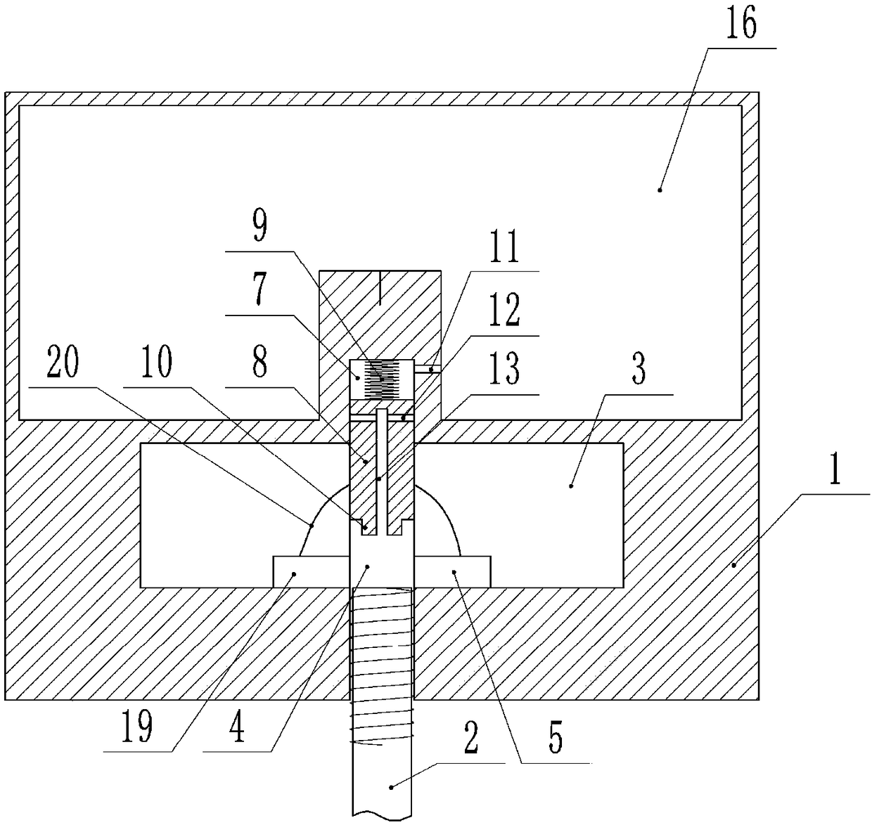
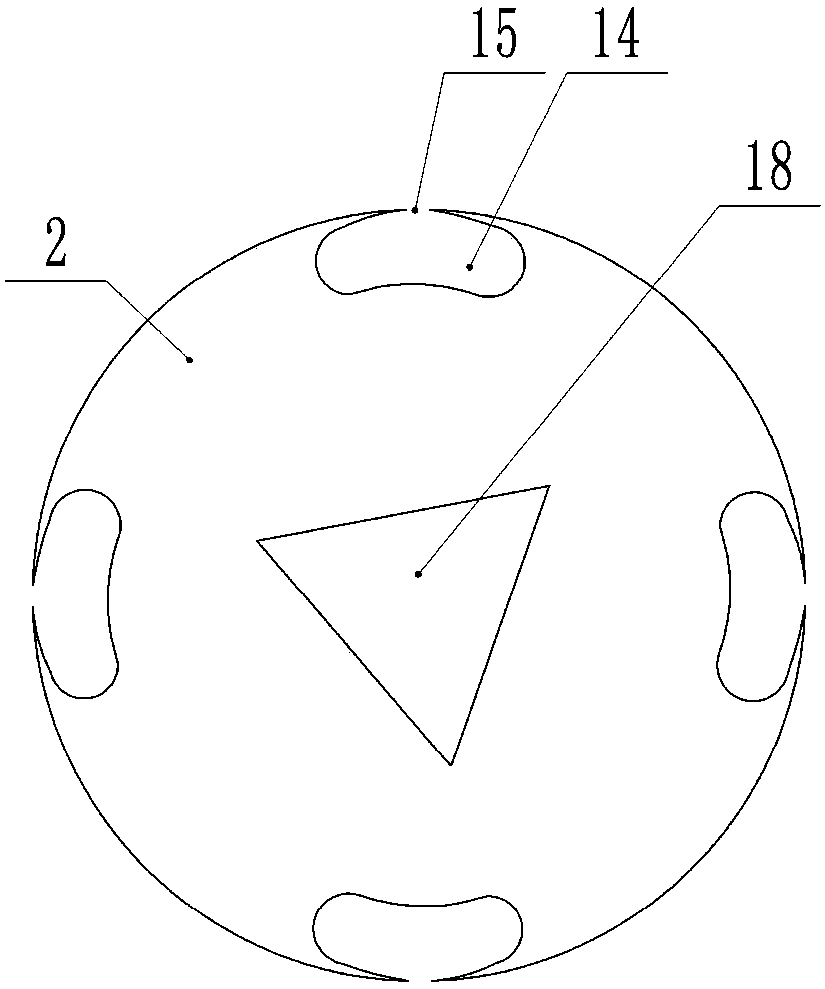
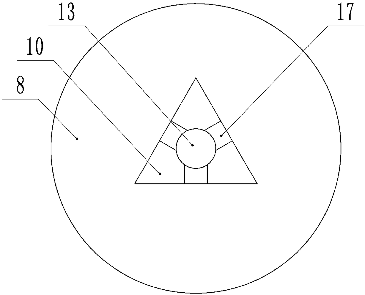
[0020] The reference signs in the drawings of the description include: clamping head 1, cutter head 2, horizontal groove 3, vertical groove 4, sleeve 5, pawl 6, sliding hole 7, slider 8, spring 9, protrusion 10, Through hole 11, water inlet hole 12, middle hole 13, through groove 14, notch 15, cavity structure 16, water guide groove 17, groove 18, string 20, protruding tooth 21.

[0021] Such as figure 1 and Figure 4 As shown, a milling cutter clamping device includes a clamping head 1 and a cutter head 2. The lower part of the clamping head 1 is processed with a cross-shaped installation groove. The installation groove includes a horizontal groove 3 and a vertical groove 4. The horizontal groove 3 is left and right. Sleeves 5 are respectively installed on the sides through bearings, the outer side of the sleeve 5 is processed with threads, the inner side of the sleeve 5 is proces...


PUM


Abstract

The invention belongs to the technical field of clamping equipment, and particularly discloses a milling cutter clamping device. The milling cutter clamping device comprises a clamping head and a cutting head, a crossed-shaped mounting groove is formed in the lower part of the clamping head, and the mounting head comprises a transverse groove and a vertical groove. Sleeves which are rotatably connected with the transverse groove are arranged at the positions, on both sides of the vertical groove, of the transverse groove, threads are arranged on the outer sides of the sleeves, and convex teethare arranged on the inner walls of the sleeves in the circumferential direction. Ratchets are hinged to the positions, on the inner sides of the sleeves, of the transverse groove, and the ratchets abut against the convex teeth. The cutting head is provided with threads which are matched with the threads on the outer sides of the sleeves. The milling cutter clamping device is mainly used for clamping the cutter head of a milling machine, and solves the problem that the machining efficiency of parts is reduced due to the low speed of changing the milling cutter.

Description

technical field [0001] The invention belongs to the technical field of clamping equipment, and specifically discloses a milling cutter clamping device. Background technique [0002] A milling machine is a machine tool that uses a milling cutter to mill a workpiece. In addition to milling planes, grooves, gear teeth, threads and spline shafts, milling machines can also process more complex profiles, with higher efficiency than planers, and are widely used in machinery manufacturing and repair departments. [0003] Before machining parts with a milling machine, install the matching milling cutter according to the size of the groove to be processed. Before installing the milling cutter, you need to loosen the clamping device of the milling cutter, install the milling cutter to be installed on the clamping device, and The device clamps the milling cutter; when the milling cutter needs to be replaced again, the operation must be repeated, which slows down the speed of replacing ...

Claims


Application Information

Patent Timeline
Patent Type & Authority Applications(China)
IPC IPC(8): B23Q3/12B23Q11/10
CPCB23Q3/12B23Q11/10
Inventor 钟志希
Owner 重庆市耀植机械有限责任公司
Why Eureka
Try Eureka