
Thermal spraying device for short shaft part

A thermal spraying, short-axis technology, applied in coating, fusion spraying, metal material coating process and other directions, can solve the problem of inconvenient use of thermal spraying devices and protective devices, and achieve simple combined use, convenient handling, and safe protection. good effect

Inactive Publication Date: 2015-03-25
SUZHOU FABAI TEXTILE CO LTD
View PDF5 Cites 0 Cited by
  • Summary
  • Abstract
  • Description
  • Claims
  • Application Information

AI Technical Summary

Problems solved by technology

[0003] In order to overcome the above-mentioned shortcomings, the purpose of the present invention is to provide a thermal spraying device for short shaft parts in the field, so as to solve the technical problem that the existing similar thermal spraying device and protective device are inconvenient to use in combination

Method used


Image

  • Thermal spraying device for short shaft part
  • Thermal spraying device for short shaft part
  • Thermal spraying device for short shaft part

Examples


Embodiment Construction

[0023] Now in conjunction with accompanying drawing, the present invention will be further described.

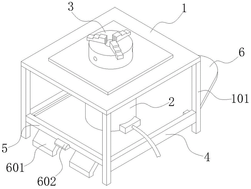
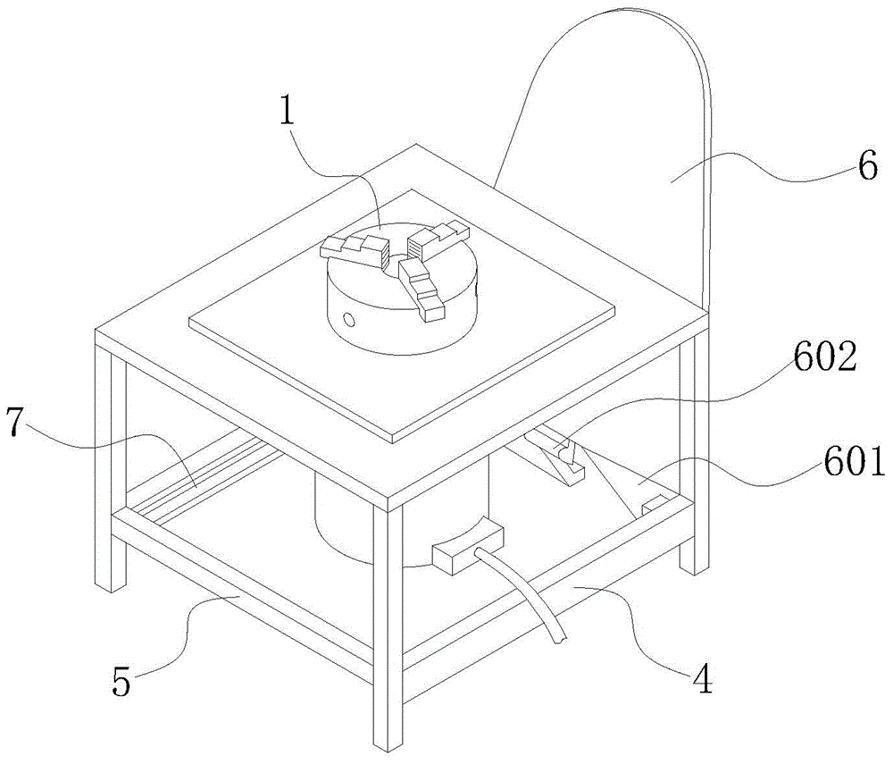
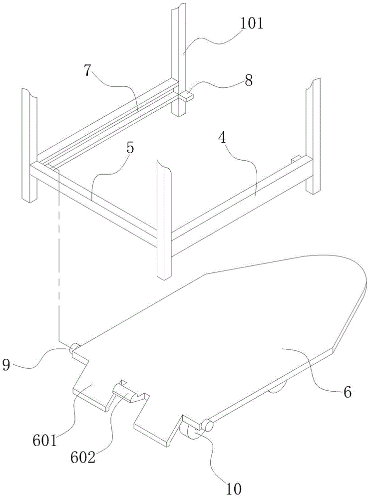
[0024] Such as figure 1 , figure 2 As shown, the short-axis thermal spraying device includes a frame 1, a motor 2, a three-jaw chuck 3, and a protective plate 6. The top surface of the frame 1 is the working surface, and the lower part of the working surface is fixedly connected to the motor 2 through a bracket, and the output of the motor 2 is The shaft passes through the working surface and is connected with the three-jaw chuck 3 through a transmission member. The lower part of the frame 1 is a supporting member 101. The supporting member 101 includes four supporting legs, and two mutually parallel guiding bars 4 and a limiting bar 5 for limiting are formed between the supporting legs. One end of the protective plate 6 is provided with a supporting foot 601 which is inclined with respect to the surface of the protective plate 6 . The two sides of the protective plate 6 ...


PUM


Abstract

The invention relates to a thermal spraying device for a short shaft part. The thermal spraying device comprises a rack, a motor, a workpiece clamp and a protection plate in sliding fit with the rack, wherein supporting legs which are inclined relative to the surface of the protection plate are arranged at one end of the protection plate, and when the protection plate slides to one sliding limit end relative to the rack, the protection plate is positioned at the bottom of the rack and the support legs are not contacted with the rack placing surface; when the protection plate slides to the other sliding limit end relative to the rack and turns over, the support legs are contacted with the rack placing surface and support the protection plate, so that the protection plate shields the rack and one side of the workpeice clamp. With the adoption of the structure, the protection plate can be drawn out when thermal spraying operation is performed, and the protection plate can be stored after the thermal spraying operation is finished; and compared with the conventional thermal spraying protection measure, the thermal spraying device for the short shaft part has a simple structure, is more convenient to use and operate, facilitates overall transportation and improves convenience of combined use.

Description

technical field [0001] The invention relates to thermal spraying equipment, which is a thermal spraying device for a short shaft part. Background technique [0002] Thermal spraying is a surface strengthening technology and an important part of surface engineering technology. It has always been a new technology project that has been promoted in my country. It is a technology that heats metal or non-metal materials in shape to a molten or semi-molten state, and then sprays them on the surface of the pretreated substrate at a certain speed by means of the flame itself or compressed air, and deposits them to form a surface coating with various functions. . Because thermal spraying is widely used, a specific thermal spraying device is generally required for specific workpieces to perform thermal spraying operations. For example, some shorter workpieces can be directly clamped by the chuck, and the motor drives the chuck to rotate, and the thermal spraying operation is performed ...

Claims


Application Information

Patent Timeline
IPC IPC(8): C23C4/00C23C4/12
CPCC23C4/00
Inventor 陈建忠
Owner SUZHOU FABAI TEXTILE CO LTD
Learn More