
Oil pipe anti-overflow tool for direct flushing and indirect flushing

A well tubing, forward and backwashing technology, which is applied in the direction of flushing the wellbore, wellbore/well components, earthwork drilling and production, etc., can solve the problems of personal injury at the gate, difficult recovery, and inability to cut off the cable, etc., to extend the full flow of the tubing The time, the effect of speeding up the work progress

Inactive Publication Date: 2015-03-25
SHANGHAI QISHAN INSTR TECH
View PDF0 Cites 6 Cited by
  • Summary
  • Abstract
  • Description
  • Claims
  • Application Information

AI Technical Summary

Problems solved by technology

[0002] After the completion of the well, for the perforation of oil and gas wells, a series of production activities carried out on the site are called perforation operations, including piling, derrick erection, installation of Christmas trees, oil delivery and discharge pipes, and perforation. The authorized announcement number is CN200985767.Y, The date of authorization announcement is December 5, 2007. The patent name is blowout prevention device for perforation operation. During the process of the well string, the drilling fluid will grow out of the tubing and casing, and the drilling fluid overflowing from the casing can be recovered by diversion of the pipeline, but the drilling fluid sprayed and overflowed in the tubing is not easy to control, and it is not good Recycling directly affects the progress of the construction work

Method used


Image

  • Oil pipe anti-overflow tool for direct flushing and indirect flushing
  • Oil pipe anti-overflow tool for direct flushing and indirect flushing

Examples


Embodiment Construction

[0016] The present invention will be described in further detail below in conjunction with the accompanying drawings and specific embodiments.

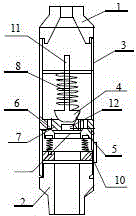
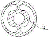
[0017] like figure 1 Shown: a positive and reverse oil tubing overflow prevention tool, including an upper joint 1, a lower joint 2 and an anti-overflow body 3, the upper joint 1 is connected with a centralizing rod 11, and the centralizing rod 11 is connected with a reverse valve 4. The reverse valve 4 is connected with a reverse valve seat 5, the length of the centralizing rod 11 is 15-35cm, the centralizing rod 11 is provided with a valve spring 8, and the valve spring 8 is connected to The reverse valve seat 4 is connected, one end of the reverse valve seat 5 is connected with a forward spline type circumferential through hole 6, and the other end of the reverse valve seat 5 is connected with a reverse valve hole 12 , the anti-overflow body 3 is provided with a normally open through hole 7, the lower end of the anti-overflow body...


PUM


Abstract

The invention discloses an oil pipe anti-overflow tool for direct flushing and indirect flushing, and relates to the field of industrial machinery. The oil pipe anti-overflow tool comprises an upper connector, a lower connector and an anti-overflow body, wherein the upper connector is connected with a righting rod which is connected with a reverse valve, the reverse valve is connected with a reverse valve base, a valve spring is arranged on the correcting rod and connected with the reverse valve, one end of the reverse valve base is connected with a forward spline type circumferential through hole, and the other end of the reverse valve base is connected with a reverse valve through hole. Normally-opened through holes are formed in the anti-overflow body. The lower end of the anti-overflow body is connected with a piston body which is connected with piston body springs. Two flow-limiting aperture passageways are designed and arranged, and therefore it can be ensured that a tubular column can be smoothly descended under the condition that no spraying or spoiling happens to an oil pipe, circulating direct and indirect flushing can be sufficiently conducted multiple times, the flow limiting effect is not changed when the tubular column is descended, and therefore the work schedule is effectively accelerated. The oil pipe anti-overflow tool is simple and ingenious in design and convenient to apply and popularize.

Description

technical field [0001] The invention relates to the field of industrial machinery, in particular to an anti-overflow tool for positive and negative well flushing oil pipes. Background technique [0002] After the completion of the well, for the perforation of oil and gas wells, a series of production activities carried out on the site are called perforation operations, including piling, derrick erection, installation of Christmas trees, oil delivery and discharge pipes, and perforation. The authorized announcement number is CN200985767.Y, The date of authorization announcement is December 5, 2007. The patent name is blowout prevention device for perforation operation. During the process of the well string, the drilling fluid will grow out of the tubing and casing, and the drilling fluid overflowing from the casing can be recovered by diversion of the pipeline, but the drilling fluid sprayed and overflowed in the tubing is not easy to control, and it is not good Recycling di...

Claims


Application Information

Patent Timeline
Patent Type & Authority Applications(China)
IPC IPC(8): E21B21/10
CPCE21B21/10
Inventor 倪前东
Owner SHANGHAI QISHAN INSTR TECH
Learn More