Two-way passageway check valve and method for conducting sand-flushing through the same

A two-way channel and one-way valve technology, which is applied in the direction of flushing wellbore, earthwork drilling, wellbore/well components, etc., can solve the problems of large flowback channel cross-section, low flowback flow rate, and inability to carry out reverse circulation flushing, etc. , to achieve the effect of smaller channel cross-section, increased flowback flow rate, and improved sand washing effect

Active Publication Date: 2015-03-25
PETROCHINA CO LTD
View PDF4 Cites 4 Cited by
  • Summary
  • Abstract
  • Description
  • Claims
  • Application Information

AI Technical Summary

Problems solved by technology

[0010] The purpose of the present invention is to solve the problem that the existing method of positive circulation sand flushing with rotary jet cannot carry out reverse circulation well flushing, and when the positive circulation sand flushing operation is performed, the cross section of the flowback channel is relatively large, resulting in a small flowback velocity question

Method used


Image

  • Two-way passageway check valve and method for conducting sand-flushing through the same
  • Two-way passageway check valve and method for conducting sand-flushing through the same

Examples


Embodiment 1

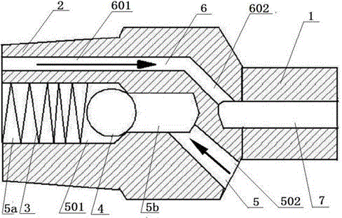
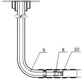
[0037] like figure 1 and figure 2 As shown, the upper end of the two-way channel check valve 8 is provided with an upper joint 1 for connecting with the rotary jet sand washing device 10, and the lower end is provided with a lower joint 2 for connecting with the oil pipe 9, and the upper joint 1 is provided with a diversion channel. 7. The lower joint 2 is provided with a forward channel 6 and a reverse channel 5 parallel to the forward channel 6 , and the reverse channel 5 is provided with a valve ball 4 and a spring 3 .

[0038] During positive circulation flushing, the flushing fluid enters the forward channel 6 from the tubing 9, and the spring 3 is compressed due to the thrust of the flushing fluid, so that the spring 3 and the valve ball 4 are in closer contact, and the gap between the two is smaller , the valve ball 4 is closed, the well washing fluid flows into the diversion channel 7 through the forward channel 6, and then enters the rotary jet sand washing device 1...

Embodiment 2

[0041] On the basis of embodiment 1, further, such as figure 1 As shown, the forward channel 6 includes a horizontal forward channel 601 and an oblique forward channel 602, the horizontal forward channel 601 communicates with the oblique forward channel 602, and the oblique forward channel 602 communicates with the guide channel 7 .

[0042]During positive circulation flushing, the flushing fluid enters the forward channel 6 from the tubing 9, and the spring 3 is compressed due to the thrust of the flushing fluid, so that the spring 3 and the valve ball 4 are in closer contact, and the gap between the two is smaller , the valve ball 4 is closed, the well flushing fluid first enters the horizontal forward passage 601 in the forward passage 6, and then enters the oblique forward passage 602. Due to the inclination of the oblique forward passage 602, under the action of gravity, the well flushing The liquid flows into the diversion channel 7 and enters the rotary jet sand washer...

Embodiment 3

[0045] On the basis of Embodiment 1, the reverse channel 5 includes a horizontal reverse channel 501 and an oblique reverse channel 502, the horizontal reverse channel 501 communicates with the oblique reverse channel 502, and the oblique reverse channel 502 is downward tilt.

[0046] During positive circulation flushing, the flushing fluid enters the forward channel 6 from the tubing 9, and the spring 3 is compressed due to the thrust of the flushing fluid, so that the spring 3 and the valve ball 4 are in closer contact, and the gap between the two is smaller , the valve ball 4 is closed, the flushing fluid enters the forward passage 6, then enters the diversion passage 7, and enters the rotary jet sand washer 10, and the well flushing fluid drives the rotary jet sand flusher 10 to form a rotary jet and pressure vibration in the horizontal well section , under the impact and agitation of the flushing fluid, the consolidated sand accumulation in the horizontal well section is ...


PUM


Abstract

The invention provides a two-way passageway check valve and a method for conducting sand-flushing through the two-way passageway check valve. The two-way passageway check valve is connected between a rotating jetting sand flushing device and an oil pipe. An upper connector used for being connected with the rotating jetting sand flushing device is arranged at the upper end of the two-way passageway check valve, and a lower connector used for being connected with the oil pipe is arranged at the lower end of the two-way passageway check valve. A diversion passageway is arranged in the upper connector. A forward passageway is arranged at the inner upper end of the lower connector, and a reverse passageway is arranged in the inner lower end of the lower connector. A valve ball and a spring are arranged in the reverse passageway. Compared with an existing liquid backflow passageway oil sleeve annulus, the passageway section is obviously narrowed, the liquid backflow speed is obviously increased, the liquid backflow speed is effectively increased under the condition of the same delivery capacity, the shaft sand grain suspension and backflow of a horizontal well section are facilitated, and the horizontal wall sand flushing effect is improved.

Description

technical field [0001] The invention belongs to a two-way channel single-flow valve and a method for flushing sand and wells by using the two-way channel single-flow valve. Background technique [0002] At present, there are mainly two types of sand washing technologies for horizontal wells: continuous sand washing technology and discontinuous sand washing technology. [0003] Continuous sand washing technology is mainly representative of coiled tubing continuous sand washing technology, ordinary tubing downhole reversing continuous sand washing technology, and concentric pipe continuous sand washing technology; [0004] Coiled tubing sand washing technology has high sand washing efficiency, simple pipe string structure, and convenient operation, but it is expensive. For horizontal wells with complex well trajectory and long horizontal section, it is easy to cause bending or even locking and buckling when the pipe string is run in. Field application limited; [0005] Ordin...

Claims


Application Information

Patent Timeline
IPC IPC(8): E21B21/10E21B21/00
CPCE21B21/00E21B21/10
Inventor 李大建曾亚勤甘庆明吕亿明牛彩云王百李亚洲朱洪征崔文昊常莉静
Owner PETROCHINA CO LTD
Why Eureka
Try Eureka