Air motor automatic reversing mechanism

A technology of automatic reversing and air motors, which is applied in the direction of engine components, machines/engines, mechanical equipment, etc., can solve the problems of shortening the service life of reversing devices, reducing the reliability of reversing devices, and failure of reversing devices, so as to avoid The effect of reducing reliability, improving reliability, and resetting in time

Active Publication Date: 2017-01-18
CHONGQING GUOLING MACHINERY
View PDF7 Cites 1 Cited by
  • Summary
  • Abstract
  • Description
  • Claims
  • Application Information

AI Technical Summary

Problems solved by technology

[0004] 1) Compressed air directly enters the control channel through the intake channel. If the compressed air source contains a lot of impurities, the impurities will enter the control channel along with the compressed air, which will easily cause reversing failure and shorten the service life of the reversing device. ;
[0005] 2) There is a "dead point". When the reversing piston drives the slider to slide up and down, when the upper and lower symmetrical center of the slider stays at the upper and lower symmetrical center of the air distribution chamber cavity, the upper cavity of the cylinder on the air distribution block will receive air The inlet and the air inlet of the lower chamber of the cylinder are blocked by the slider at the same time (commonly known as "dead point"), which leads to the failure of the reversing device and reduces the reliability of the reversing device

Method used


Image

  • Air motor automatic reversing mechanism
  • Air motor automatic reversing mechanism

Examples


Embodiment Construction

[0029] The present invention will be further described below in conjunction with the accompanying drawings and specific embodiments, so that those skilled in the art can better understand the present invention and implement it, but the examples given are not intended to limit the present invention.

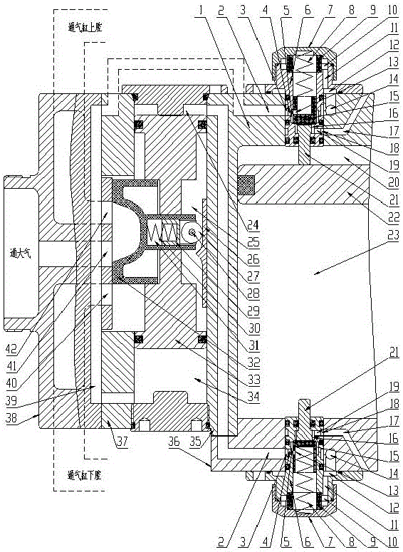
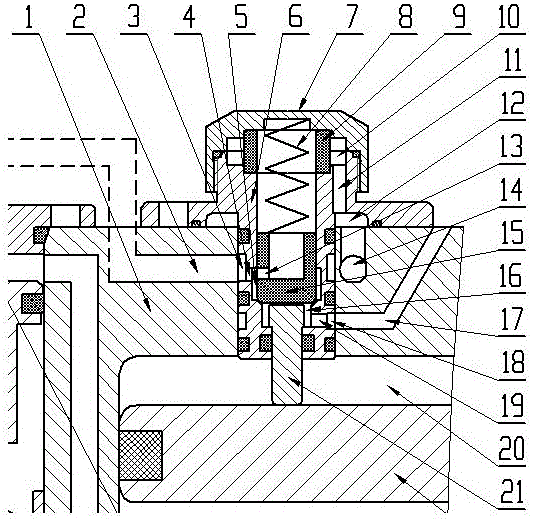
[0030] Such as figure 1 Shown is a schematic structural view of an embodiment of the automatic reversing mechanism of the air motor of the present invention. An automatic reversing mechanism of an air motor, comprising a cylinder 35, the upper and lower ends of the cylinder 35 are respectively provided with a cylinder top wall 1 and a cylinder lower cover 36, and the cylinder top wall 1 and the cylinder lower cover 36 are respectively provided with pilot valves, and the cylinder top A piston chamber is arranged between the wall 1 and the cylinder lower cover 36, and a piston 22 is arranged in the piston chamber, and the cylinder upper chamber 20 is formed between the piston 22 and...


PUM


Abstract

The invention discloses an automatic reversing mechanism for a pneumatic motor. The automatic reversing mechanism comprises an air cylinder; an air cylinder top wall and an air cylinder lower cover are arranged at the upper and lower ends of the air cylinder; pilot valves are arranged on the air cylinder top wall and the air cylinder lower cover respectively; a piston cavity is formed between the air cylinder top wall and the air cylinder lower cover; a piston is arranged in the piston cavity; a reversing valve is arranged on the air cylinder, and comprises a reversing valve body; a reversing piston cavity is formed in the reversing valve body; a reversing piston is arranged in the reversing piston cavity; a reversing piston upper cavity, an air distributing chamber cavity and a reversing piston lower cavity are formed between the reversing piston and the reversing piston cavity; control passages, air intake passages communicated with an air source and exhaust passages communicated with air are formed in the air cylinder top wall and the air cylinder lower cover respectively; the exhaust passages are formed in the inner sides, near the piston cavity, of the air intake passages; the control passage formed in the air cylinder top wall is communicated with the reversing piston lower cavity; the control passage formed in the air cylinder lower cover is communicated with the reversing piston upper cavity.

Description

technical field [0001] The invention belongs to the technical field of reversing control of an air motor, and in particular relates to an automatic reversing mechanism of an air motor. Background technique [0002] In the existing air motor reversing mechanism, there are only two channels on the pilot valve body, the air intake hole that is normally connected to the air source and the control air hole that controls the action of the reversing mechanism, and there is no exhaust hole. It is a two-position two-way valve structure. . There is an exhaust hole on the upper and lower end covers of the piston chamber of the reversing mechanism. When the pilot valve stem is in the closed position (the piston in the cylinder does not touch the pilot valve stem), the control air hole and the air inlet hole on the pilot valve body are separated. , when the pilot valve stem is in the open position (the piston in the cylinder pushes the pilot valve stem away), the control air hole on the...

Claims


Application Information

Patent Timeline
Patent Type & Authority Patents(China)
IPC IPC(8): F01B25/02F01B25/08
CPCF01B25/02F01B25/08
Inventor 龙江
Owner CHONGQING GUOLING MACHINERY
Why Eureka
Try Eureka