Engine braking method

A technology of engine braking and engine, which is applied in engine control, engine components, machine/engine, etc., can solve the problems of limited application, poor reliability and durability of hydraulically driven valve opening, complex structure and control, etc., and achieves wide application, Optimal braking performance, easy manufacturing and assembly

Inactive Publication Date: 2015-03-25
SHANGHAI UNIVERSOON AUTOPARTS CO LTD
View PDF4 Cites 13 Cited by
  • Summary
  • Abstract
  • Description
  • Claims
  • Application Information

AI Technical Summary

Problems solved by technology

[0007] The object of the present invention is to provide an engine braking method, which solves the technical problems in the prior art of complex structure and control, poor reliability and durability of hydraulically driven valve opening, and limited application

Method used


Image

  • Engine braking method
  • Engine braking method
  • Engine braking method

Examples


Embodiment 1

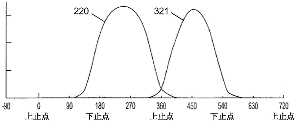
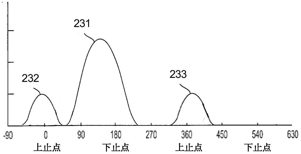
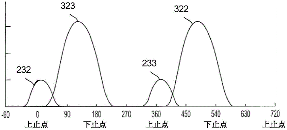
[0035] Figure 1 to Figure 6 Embodiment 1 is used to describe the engine braking method of the present invention. figure 1 It is a schematic diagram of the engine braking control of the present invention. Normal ignition operation of the engine 10 in accordance with figure 1 The solid arrow on the left in the center runs. At this time, the engine brake control mechanism 50 is closed (not powered), and the axial drive mechanism 100 of the cam roller biases the cam roller 235 at the first axial position, and the cam roller 235 is connected with the conventional ignition cam 230, and the conventional ignition cam The movement of 230 is transmitted to the valves, resulting in the normal firing operation of the engine 10 . Switch to figure 1 The dotted arrow on the right in the center runs. At this time, the brake control mechanism 50 of the engine is turned on (energized), and the axial drive mechanism 100 of the cam roller moves the cam roller 235 from the first axial positi...

Embodiment 2

[0042] In this embodiment, on the basis of the first embodiment above, the engine braking operation of the intake valve is added. Both the exhaust valve actuator and the intake valve actuator have the axial drive mechanism 100 of the cam roller, the structure, principle and operation process of which are the same as those described in Embodiment 1 above, and will not be repeated here.

[0043] This embodiment includes four cams: a conventional ignition exhaust cam 230, a braking exhaust cam 2302, a conventional ignition intake cam and a braking intake cam (one more than embodiment 1). use the intake cam). When the engine needs conventional ignition operation, the axial driving mechanism 100 of the cam roller biases the cam roller 235 at the first axial position, and the intake and exhaust cam rollers are connected or adjacent to the conventional ignition intake and exhaust cams, and the conventional The movement of the ignition intake and exhaust cams is transmitted to the va...

Embodiment 3

[0046] In this embodiment, on the basis of the above-mentioned embodiment 1 or embodiment 2, an operation of modifying the movement of the valve is added. The principle is to add a Lost Motion mechanism to a valve actuator, such as a rocker arm, and the Lost Motion mechanism is connected to at least one valve. Through the opening and closing of the motion loss mechanism, the movement of the valve connected with the motion loss mechanism is changed. In this way, on the basis of the valve movement obtained in the above-mentioned embodiment 1 or embodiment 2, a new valve movement is added.


PUM


Abstract

The invention discloses an engine braking method. A cam roller is moved by an axial driving mechanism of the cam roller from a first axial position to a second axial position on a roller shaft, connection between the cam roller and a conventional ignition cam is switched into connection between the cam roller and an engine braking cam, movement of a conventional ignition valve stops, and movement of a braking valve of an engine is generated. The axial driving mechanism of the cam roller can be integrated in a valve actuator such as a rocker arm and can also be located outside the valve actuator; for example, the axial driving mechanism of the cam roller is fixed to the engine. By means of the engine braking method, high-power braking generated by the special braking cam is obtained, the special braking cam can only comprise a braking exhaust cam body and can also comprise the braking exhaust cam body and a braking admission cam body at the same time, engine braking is constructed as non-hydraulic fixed-chain type bearing, and the efficacy losing mode of hydraulic bearing is avoided. The braking control is simple, the braking performance is excellent, the structure is simple and compact, manufacturing and assembling are easy, and the application range is wide.

Description

Technical field: [0001] The invention relates to the mechanical field, in particular to the field of engine braking, in particular to an engine braking method. Background technique: [0002] In the prior art, the engine braking technology is widely known, which only needs to temporarily convert the engine generating power into an air compressor absorbing energy. Fuel is cut off during the transition, and the valve is opened near the end of the engine piston's compression stroke, allowing the compressed gas (air during braking) to be released. The energy absorbed by the engine in compressing the gas during the compression stroke cannot be returned in the subsequent expansion stroke to the engine piston, but dissipated through the engine's exhaust and cooling system. The end result is effective engine braking that slows the vehicle. [0003] A precedent for an engine braking device is disclosed by U.S. Patent No. 3,220,392 provided by Cummins. The invention of this patent ut...

Claims


Application Information

Patent Timeline
Patent Type & Authority Applications(China)
IPC IPC(8): F02D13/04F01L13/06
Inventor 杨洲奚勇
Owner SHANGHAI UNIVERSOON AUTOPARTS CO LTD
Why Eureka
Try Eureka