
Lobe bearing

A technology of bearings and oil vanes, applied in the field of bearings, can solve the problems of poor stability and poor economy of the bearing system, achieve the effects of reducing operating costs, reducing processing difficulty, and improving stability

Active Publication Date: 2015-03-25
DONGFANG TURBINE CO LTD
View PDF6 Cites 3 Cited by
  • Summary
  • Abstract
  • Description
  • Claims
  • Application Information

AI Technical Summary

Problems solved by technology

[0004] The purpose of the present invention is to design an adjustable oil vane bearing to solve the above-mentioned disadvantages brought by the existing oil vane bearing to processing, disassembly and maintenance, as well as poor economy and poor stability of the bearing system.

Method used


Image

  • Lobe bearing
  • Lobe bearing
  • Lobe bearing

Examples


Embodiment 1

[0024] Embodiment 1, taking the four-lobe bearing with the bearing body 1 as a complete ring structure as an example, the details are as follows:

[0025] see Figure 5 , the oil leaf bearing includes a bearing body 1, a Ujin tile 2 and a Ujin tile support slider 4, and the Ujin tile 2 is poured on the Ujin tile support slider 4 to form an integral structure, and the profile line of the working surface is a leaf shape. The bearing body 1 is a ring-shaped structure, and its inner wall is provided with 4 circumferentially distributed radial bottomed chutes, and each chute is equipped with a Ujin tile support slider 4 that has been poured with Ujin tile 2, which can be placed in the chute. slide. The Wujin tile 2 on the slider 4 faces the center of the bearing circle, and there are screw holes and fastening bolts 6 on the back of the slider 4; corresponding bolt holes are opened at the bottom of the chute of the bearing body, and the fastening bolts 6 run through the Bolt holes...

Embodiment 2

[0027] In the second embodiment, a four-lobe bearing with two halves of the bearing body 1 is taken as an example.

[0028] see Figure 6 , The oil leaf bearing includes a bearing body 1, a Ujin tile 2 and a Ujin tile support slider 4, and its specific structure is similar to Embodiment 1. However, in order to further facilitate bearing processing, disassembly, and maintenance, the bearing body 1 adopts a split structure, which is divided into two halves, the lower half bearing body 1-1 and the upper half bearing body 1-2. 8 Tighten it into one piece.


PUM


Abstract

The invention discloses a lobe bearing, which comprises a bearing body, white metal pads and white metal pad supporting slide blocks, wherein the white metal pads are poured on the white metal pad supporting slide blocks, and the working face molded line of the bearing is of lobe type or wedge type; the bearing body is of an annular structure, and a plurality of circumferentially distributed radial chutes with bottoms are arranged on the inner wall of the bearing body; each white metal pad supporting slide block poured with the white metal pad is arranged in each corresponding chute and can slide in the chute, and the white metal pad on the slide block faces the center of a circle of the bearing; screw holes and fastening bolts are formed in the back of the slide block, and bolt holes corresponding to the screw holes and the fastening bolts are formed in the bottom of the chute of the bearing body; the fastening bolts penetrate through the bolt holes and are screwed into the screw holes in the back of the slide block, so that the slide block is tightly fixed on the bearing body; an adjusting gasket is arranged at the bottom of the chute. The white metal pad sand the bearing body are of split structures, and are processed by only considering the precision of molded line without considering the dimensional precision of a gap, so that the processing difficulty is reduced; the bearing can be replaced or repaired after partially worn, so that the operating cost is reduced; the bearing has multiple supporting surfaces, so that the stability of rotor operation is improved.

Description

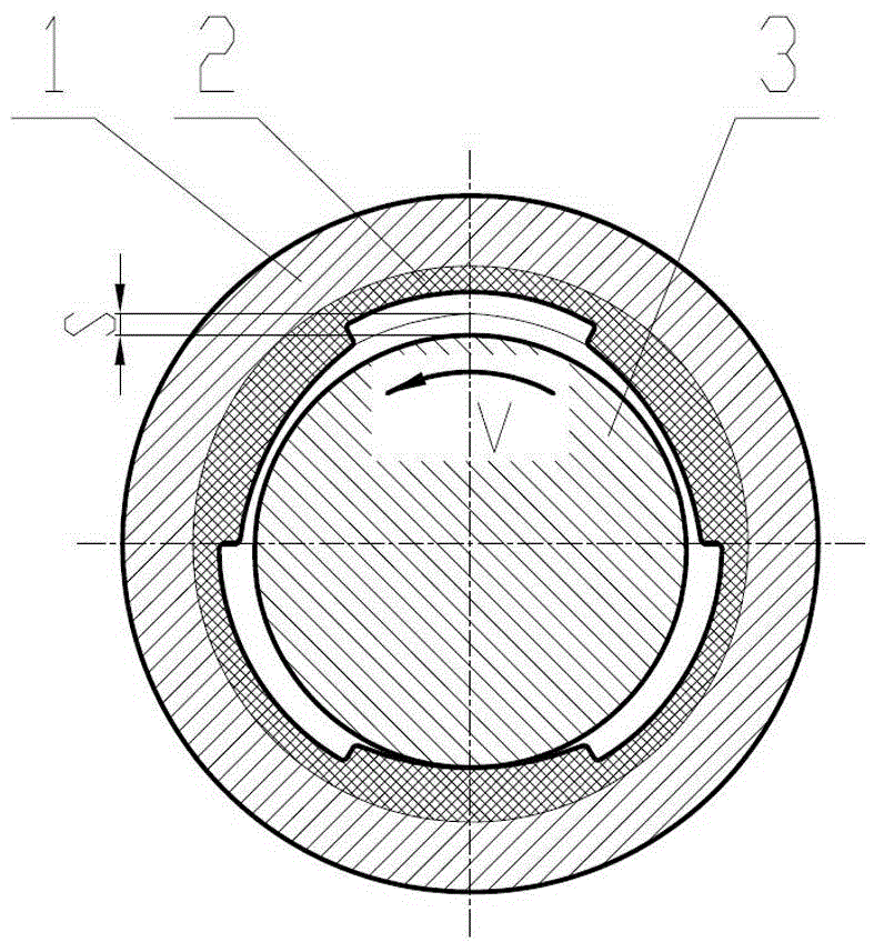
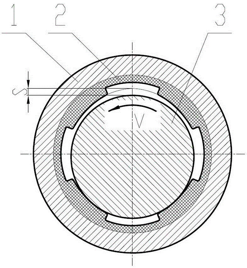
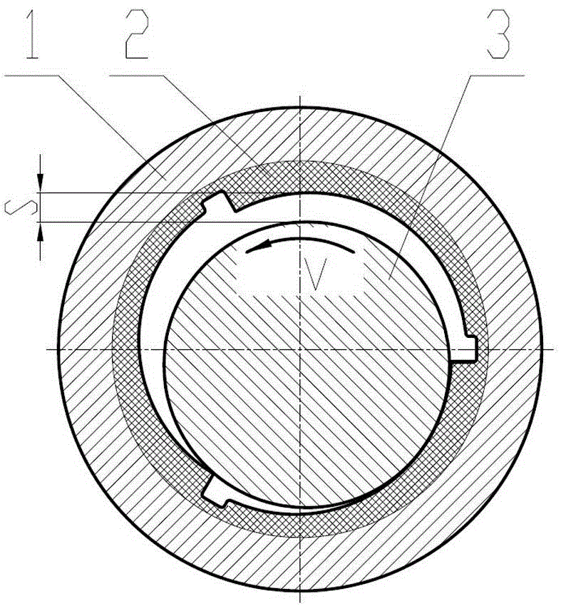
technical field [0001] The invention relates to a bearing, in particular to an oil leaf bearing. Background technique [0002] Main shaft bearings of large high-speed rotating machines such as steam turbines usually use oil leaf bearings, such as Figure 1~4 As shown, the bearing is composed of a bearing body 1 and a black tile 2, and the black tile 2 is cast in the bearing body 1. There is a gap s between the Wujin tile 2 and the main shaft 3. When the main shaft 3 rotates, the gap s is filled with lubricating oil to form an oil film, which avoids friction between the main shaft 3 and the Wujin tile 2, and takes away the heat to play a lubricating role. . The inner peripheral surface of Wujin tile 2 is processed into 3 or 4 working curved surfaces along the circumferential direction. There are two types of curved surface lines, specifically: one is a circular arc line, and the main shaft 3 can form an oil film when it is rotated forward or reversed, which is called an oil...

Claims


Application Information

Patent Timeline
Patent Type & Authority Applications(China)
IPC IPC(8): F16C25/02F16C33/06
Inventor 李冠孙敏郭勇孙奇王文武杨灵赵卫军周勇陈付荣刚钱勇孙伟
Owner DONGFANG TURBINE CO LTD
Learn More