Torque protection device and working principle thereof

A protection device and installation groove technology, which is applied in the direction of automatic clutches, clutches, mechanical equipment, etc., can solve problems such as burnout, failure of the reducer, cost waste, etc.

Active Publication Date: 2015-03-25
章臣重工(苏州)有限公司
View PDF10 Cites 6 Cited by
  • Summary
  • Abstract
  • Description
  • Claims
  • Application Information

AI Technical Summary

Problems solved by technology

[0004] In view of this, the present invention proposes a torque protection device and its working principle to solve the problem that the above-mentioned reducer fails to achieve the expected effect and burns out, resulting in waste of cost

Method used


Image

  • Torque protection device and working principle thereof

Examples


Embodiment

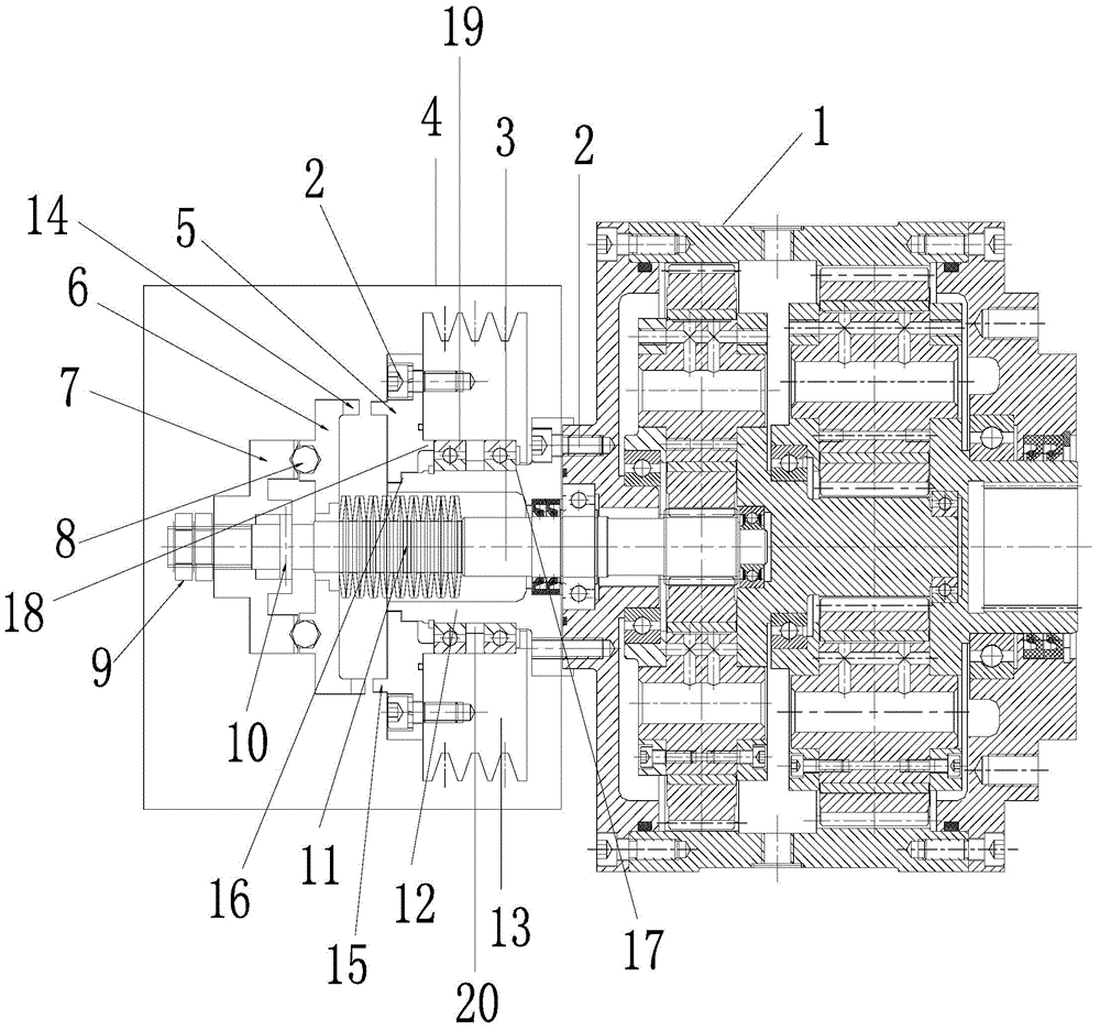
[0021] See figure 1 As shown, a torque protection device of the present invention includes a reducer, the reducer is composed of a pulley mechanism 4 and a reducer mechanism 1, the pulley mechanism 4 and the reducer mechanism 1 are connected through an input shaft 3, and the input shaft 3 is close to the reducer mechanism 1 A bearing seat 12 is set, and the bearing seat 12 is fixedly connected with the reduction mechanism 1 through a screw 2. A pulley 13 is set on the bearing seat 12, and a bearing is installed between the bearing seat 12 and the pulley 13, wherein,

[0022] The surface of the pulley 13 away from the reduction mechanism 1 is equipped with the first pressure plate 5 through the screw 2, so that when the pulley 13 rotates, the first pressure plate 5 rotates at the same time, and the left side of the first pressure plate 5 engages the second pressure plate 6, the first pressure plate 5 The teeth 15 of the pressure plate mesh with the teeth 14 of the second pressu...


PUM


Abstract

The invention discloses a torque protection device. A bearing pedestal is arranged at the position, close to a speed reduction mechanism, of an input shaft in a sleeving way, and is fixedly connected with the speed reduction mechanism through screws, wherein a belt pulley is arranged on the bearing pedestal in the sleeving way; a bearing is arranged between the bearing pedestal and the belt pulley; a first pressure plate is arranged on the surface, away from the speed reduction mechanism, of the belt pulley through a screw; the left side of the first pressure plate is meshed with a second pressure plate; a third pressure plate is arranged on the left side of the second pressure plate; a pair of locking nuts is fixed on the left side of the third pressure plate; a plurality of steel balls are arranged between the second and third pressure plates; a safety pin is arranged between the third pressure plate and the input shaft; a belleville spring is arranged on the right side of the second pressure plate. According to the torque protection device, the steel balls are additionally arranged between the second and third pressure plates, the belleville spring is arranged between the second pressure plate and the bearing pedestal, and when output force exceeds a set load, the steel balls are separated, and the first and second pressure plates are bounced off by the belleville spring, so that the rotation of the belt pulley cannot be transferred to the input shaft, and the aim of protecting a speed reducer is fulfilled.

Description

technical field [0001] The invention relates to the technical field of a reducer, in particular to a torque protection device and its working principle. Background technique [0002] The reducer is a kind of transmission, which is generally used for low-speed and high-torque transmission equipment. The principle is to use the electric motor, internal combustion engine, motor or other high-speed running power to mesh the gear with a small number of teeth on the input shaft of the reducer with the gear on the output shaft. Large gear, so as to achieve the purpose of deceleration; reducer is an independent component composed of gear transmission, worm transmission, and gear-worm transmission enclosed in a rigid shell, and is often used as a deceleration transmission between the prime mover and the working machine device. [0003] The application fields of the reducer are very wide, and the reducer can be used in almost all industries. When the reducer works frequently and for ...

Claims


Application Information

Patent Timeline
Patent Type & Authority Applications(China)
IPC IPC(8): F16D43/206
Inventor 叶权章葛岐
Owner 章臣重工(苏州)有限公司
Why Eureka
Try Eureka