Eureka AIR delivers breakthrough ideas for toughest innovation challenges, trusted by R&D personnel around the world.

Transportable power tool

a power tool and portable technology, applied in the field can solve the problems of knob b>11/b, power tools falling from the hand of users, finger grip damage, etc., and achieve the effect of reducing the cost of transportable power tools, not to be damaged, and being used stably

Inactive Publication Date: 2005-06-09
MATSUSHITA ELECTRIC WORKS LTD
View PDF13 Cites 117 Cited by
  • Summary
  • Abstract
  • Description
  • Claims
  • Application Information

AI Technical Summary

Benefits of technology

[0008] A purpose of the present invention is to provide a transportable power tool in which an operation member used for switching the operation mode may not be damaged due to bumping against the land surface or the floor face, even when the power tool is fallen or toppled down.
[0009] A transportable power tool in accordance with an aspect of the present invention comprises: a motor; a reducer-transmitter for reducing rotation speed of a driving shaft of the motor and for transmitting a driving force of the motor to an output shaft thereof; a control circuit for controlling driving of the motor; a housing for enclosing the motor, the reducer-transmitter and the control circuit; and a battery pack detachably coupled with the housing.
[0013] By such a configuration, the operation member may not be damaged due to bumping against the land surface or the floor face even when the power tool is fallen or toppled down on the land surface or the floor face. Consequently, the transportable power tool can be used stably over the long term. Furthermore, it is no need to reinforce the mechanical strength of the operation member and so on, so as not to be damaged due to the bumping. Thus, it is possible to reduce the cost of the transportable power tool.

Problems solved by technology

The conventional transportable power tool, however, has a possibility that the power tool is fallen from a hand of a user or toppled down due to careless handling.
Since the knob 11′ or the finger grip of the operation switch is provided on the outer face of the power unit 8, the knob 11′ or the finger grip could be damaged due to the falling or toppling of the power tool.
The display device, however, will be damaged, if the power tool is fallen or toppled down backend-to.

Method used


Image

  • Transportable power tool
  • Transportable power tool
  • Transportable power tool

Examples


Embodiment Construction

[0024] A transportable power tool in accordance with an embodiment of the present invention is described with reference to drawings.

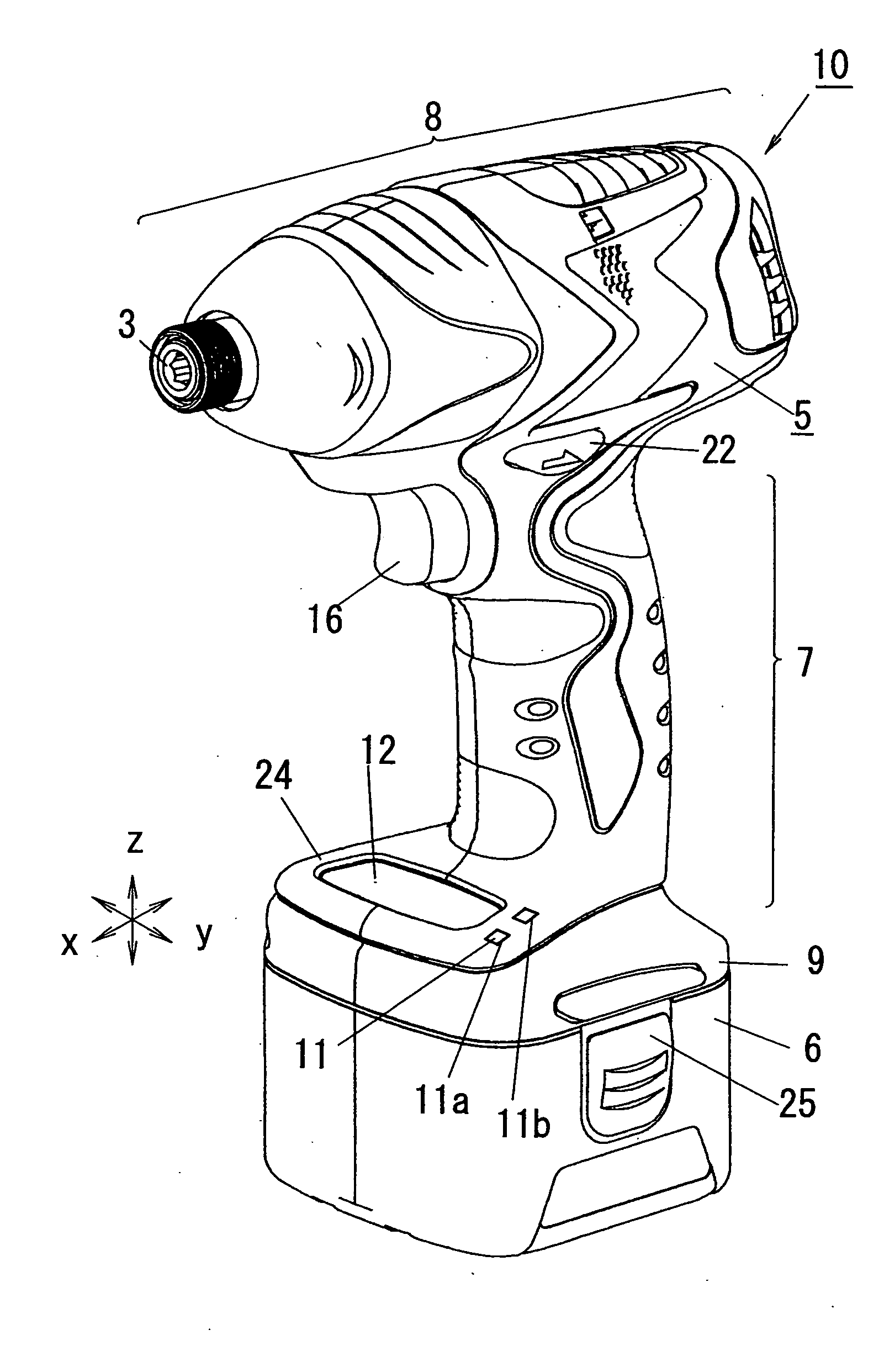
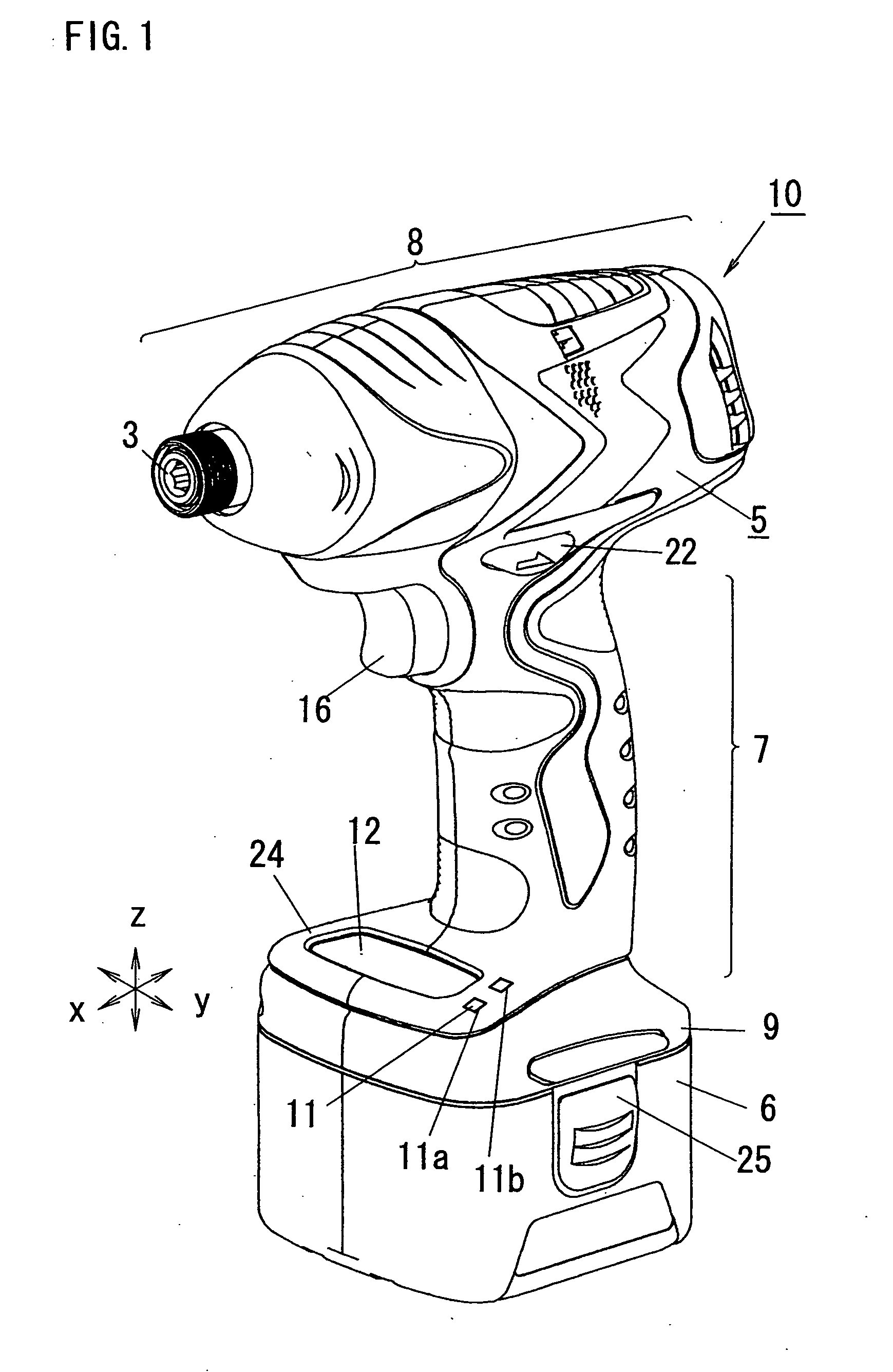
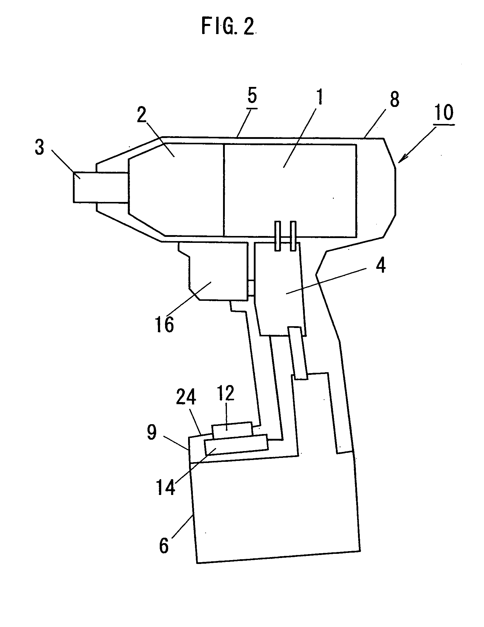
[0025] An appearance and a configuration of a transportable power tool (hereinafter, abbreviated as “power tool”) 10 in accordance with the embodiment are shown in FIG. 1. The transportable power tool 10 is, for example, an impact power tool, a power drill / driver, or the like. A block configuration of the power tool 10 is shown in FIG. 2. A detailed configuration of a main portion of the power tool 10 in the embodiment is shown in FIG. 3.

[0026] The power tool 10 comprises a motor 1, a reducer-transmitter 2 for reducing rotation speed of a driving shaft of the motor 1 and for transmitting a driving force of the motor 1 to an output shaft 3 of the reducer / transmitter 2, a switching circuit 4, a trigger lever 16 for switching on and off of the driving of the motor 1, a rotation switch lever 22 for switching the rotation direction of the motor 1 between n...


PUM

PropertyMeasurementUnit
Dimensionaaaaaaaaaa

Abstract

A transportable power tool such as an impact driver has a power unit in which a motor and a reducer-transmitter are contained, a grip and a coupler unit with which a battery pack is coupled. Maximum dimensions of the power unit and maximum dimensions of the battery pack in a direction perpendicular to both of center axes of the power unit and the grip and in a direction parallel to the center axis of the power unit are larger than those of the grip in the same directions. Operation members used for selecting an operation mode of the motor and a display device are provided at positions near to the grip from a line binding contacting portions of the power unit and the battery pack when the power unit and the battery pack are simultaneously contacted with the same plane in each state.

Description

BACKGROUND OF THE INVENTION [0001] 1. Field of the Invention [0002] The present invention relates to a transportable (or handheld) power tool used for fastening a bolt, a nut, a screwnail, and so on, for drilling metalwork, woodwork, mortar, concrete, and so on, or for cutting metalwork, woodwork, and so on. [0003] 2. Description of the Related Art [0004] A conventional transportable power tool is described with reference to FIGS. 9A and 9B. FIG. 9A is a side view of the conventional transportable power tool. As can be seen from FIG. 9A, in the conventional transportable power tool, a cylindrical shaped power unit 8 is provided at a top end of a grip 7 in a manner so that a center axis of the cylindrical shape of the power unit 8 crosses a center axis of the grip 7 at a predetermined angle near to right angle. A battery pack 6 is detachable provided at a bottom end of the grip 7. Generally, a diameter of the cylindrical shape of the power unit 8 is larger than a width of the grip 7 ...

Claims


Application Information

Patent Timeline
IPC IPC(8): B25B21/00B25F5/00B25F5/02
CPCB25F5/02B25B21/00
Inventor SHIMIZU, HIDENORIOHASHI, TOSHIHARU
Owner MATSUSHITA ELECTRIC WORKS LTD
Why Eureka
Eureka Blog
Learn More