Rotary blade device with brake and clutch functions

A technology of rotating blades and clutching, applied in the combination of couplings and brakes, mechanical equipment, etc., can solve problems such as the inability to prevent the rotation of the large gear, and the inability to act as a clutch and brake.

Inactive Publication Date: 2015-03-25
NINGBO YINZHOU LANGLIN MACHINERY
View PDF6 Cites 4 Cited by
  • Summary
  • Abstract
  • Description
  • Claims
  • Application Information

AI Technical Summary

Problems solved by technology

The braking device with this structure is only suitable for disengaging the blade from the driving device and stopping immediately when the dri

Method used


Image

  • Rotary blade device with brake and clutch functions
  • Rotary blade device with brake and clutch functions
  • Rotary blade device with brake and clutch functions

Examples


Embodiment Construction

[0021] The present invention will be further described below in conjunction with the accompanying drawings and specific embodiments.

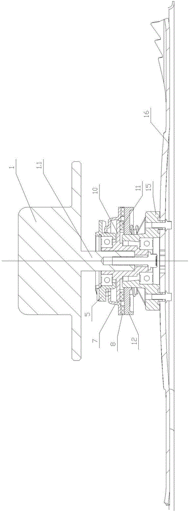
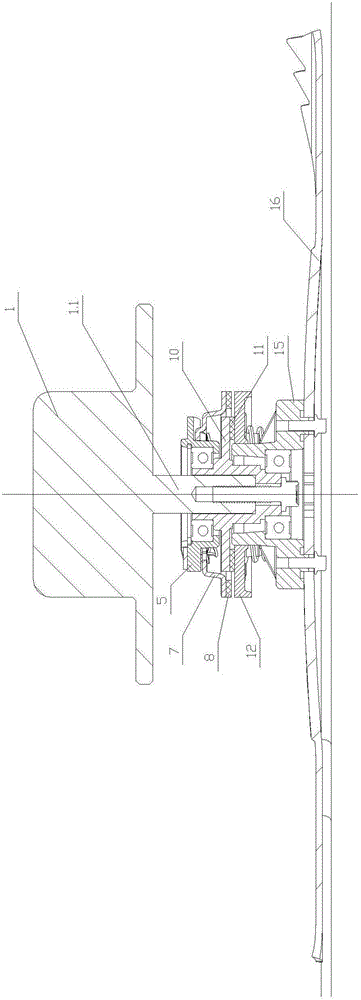
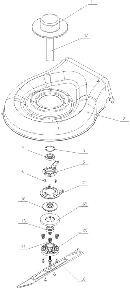
[0022] As shown in the figure, the present invention provides a kind of device with the rotating blade of brake and clutch, and it comprises chassis 2, blade 16, drive device 1 that is fixed on chassis 2 and drives blade 16 to rotate, is installed in the clutch in chassis 2 device and braking device, it also includes a driving wheel 10 with an engaging structure installed on the output shaft 1.1 of the driving device 1, and a passive wheel 12 with an engaging structure that can engage with the driving wheel 10 on the end surface. The passive wheel 12 is connected with the blade 16, and the clutch device includes a pressure device that presses the passive wheel 12 to separate from the driving wheel 10 or subtracts the pressing force on the passive wheel 12, and subtracts the The pressing force of the passive wheel 12 is a reset device that reset...


PUM


Abstract

The invention discloses a rotary blade device with brake and clutch functions. The rotary blade device comprises a bottom disc (2), a blade (16), a driving device (1), a clutch device, a brake device, a driving wheel disc (10) and a driven wheel disc (12), the driving device (1) is fixed to the bottom disc (2) and drives the blade (16) to rotate, the clutch device and the brake device are arranged in the bottom disc (2), the driving wheel disc (10) is arranged on an output shaft (1.1), and the driven wheel disc (12) capable of being meshed with the driving wheel disc (10) is arranged on the end face. The driven wheel disc (12) is connected with the blade (16), the clutch device comprises a pressure device and a resetting device, the pressure device presses the driven wheel disc (12) to enable the driven wheel disc (12) and the driving wheel disc (10) to be separate or reduce the pressure on the driven wheel disc (12), and the resetting device enables the driven wheel disc (12) to be reset to be meshed with the driving wheel disc (10) again. According to the rotary blade device with the brake and clutch functions, the blade can stop rotating immediately without shutting down an engine.

Description

technical field [0001] The invention relates to a device for rotating blades with braking and clutching functions. Background technique [0002] The blades used on lawn mowers are usually in a state of high-speed rotation. During the use of existing equipment, if the operator needs to leave for a short period of time, the engine of the equipment needs to be turned off to allow the entire equipment to process In the shutdown state, it needs to be turned on again when it is used again, and it cannot be used immediately, which is inconvenient to use; and when the existing equipment stops the rotation of the blade, due to the inertia, the blade often cannot stop rotating immediately, such as the operator or other personnel touch the blade still cause harm and lack security. [0003] The existing patent application number is 200610039565.6, which discloses a brake device and an electric tool containing the brake device, which are applied to electric tools such as hedge trimmers....

Claims


Application Information

Patent Timeline
IPC IPC(8): F16D67/02
Inventor 赵延辉
Owner NINGBO YINZHOU LANGLIN MACHINERY
Why Eureka
Try Eureka