
Chain transmission device

A chain drive and chain buckle technology, applied in the direction of transmission, transmission parts, transmission chain, etc., can solve the problems of issuing an alarm, affecting the normal operation of transmission, and not being able to give it to the staff in time, so as to achieve the effect of stable transmission.

Inactive Publication Date: 2015-03-25
NORTH CHINA UNIV OF WATER RESOURCES & ELECTRIC POWER
View PDF10 Cites 0 Cited by
  • Summary
  • Abstract
  • Description
  • Claims
  • Application Information

AI Technical Summary

Problems solved by technology

[0002] The chain transmission device is a relatively common transmission method in the mechanical transmission industry. It includes a sprocket and a chain meshing with the sprocket teeth on the sprocket. The chain is composed of multiple chain buckle units connected by rotation. Chain link, the two ends of the two connected chain links are connected by pin shafts, and the pin shafts between the chain links are equipped with chain rollers. Although such a structure can achieve the purpose of transmission, but in the application process, when the chain breaks When the chain is broken, it will affect the normal operation of the transmission; during the working process, the staff cannot be given an alarm in time after the chain breaks

Method used


Image

  • Chain transmission device
  • Chain transmission device
  • Chain transmission device

Examples


Embodiment Construction

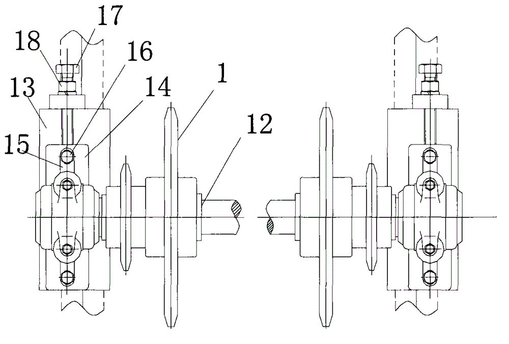
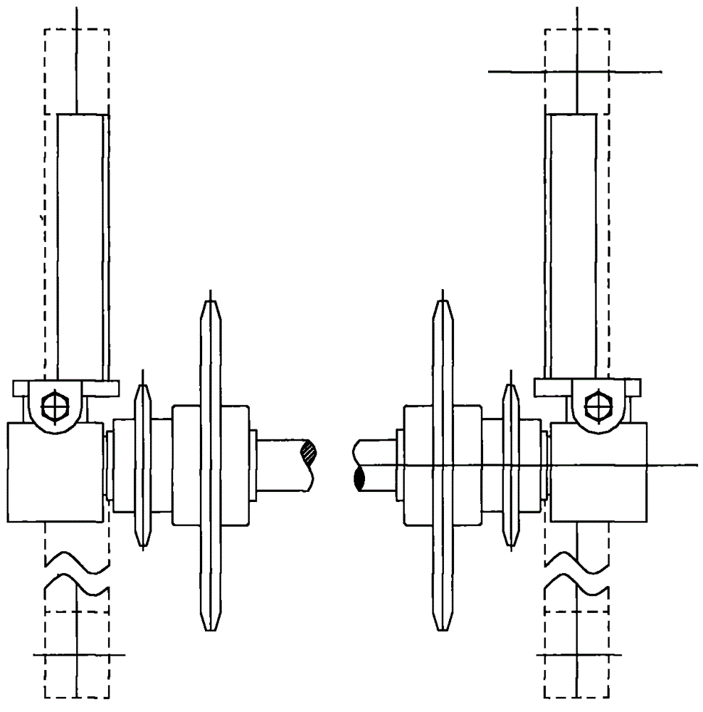
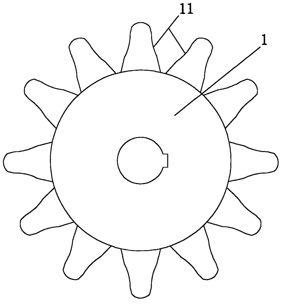
[0023] Attached below Figure 1-7 And embodiment the present invention is described in further detail.

[0024] A chain transmission device, comprising a sprocket 1 and a chain 2 engaged with the upper sprocket teeth, the chain is composed of a plurality of rotatably connected chain buckle units 3, each chain buckle unit includes two chain links 4, and the two connecting chain links The two ends are connected by a pin shaft 5, and a chain roller 6 is set on the pin shaft between the chain links. Every four chain buckle units are connected in turn to form a chain unit. The middle two chain buckle units in a chain unit There is a supporting connection seat 7 for supporting and connecting the two chain buckle units, and a lifting structure is respectively provided between the chain buckle units at both ends of the chain unit and the supporting connecting seat. The first connecting rod 8 and the second connecting rod 9 movably connected with the links in the chain buckle unit, an...


PUM


Abstract

The invention relates to a chain transmission device which comprises chain wheels and a chain. The chain is composed of a plurality of chain clasp units connected rotationally. Each chain clasp unit comprises two chain links, wherein the two ends of the two connected chain links are connected through pin shafts, and the portion, between the chain links, of each pin shaft is sleeved with a chain roller. Every four chain clasp units are connected in sequence to form a chain unit. A bearing connection base is arranged between the two chain clasp units in the middle of each chain unit and used for bearing and connecting the two chain clasp units. A lifting structure is arranged between the chain clasp unit at each end of each chain unit and the corresponding supporting connection base. In this way, after the chain clasp units break, by means of a first connection rod, a second connection rod and an elastic piece in each lifting mechanism, the bearing connection bases can keep lifting the broken chain clasp units, the whole chain can still achieve meshing of the chain wheels, still have the transmission capacity, and will not lose the transmission capacity when certain chain clasp units break suddenly, and chain transmission is effectively guaranteed.

Description

technical field [0001] The invention relates to the technical field of mechanical transmission, in particular to a chain transmission device. Background technique [0002] The chain transmission device is a relatively common transmission method in the mechanical transmission industry. It includes a sprocket and a chain meshing with the sprocket teeth on the sprocket. The chain is composed of multiple chain buckle units connected by rotation. Chain link, the two ends of the two connected chain links are connected by pin shafts, and the pin shafts between the chain links are equipped with chain rollers. Although such a structure can achieve the purpose of transmission, but in the application process, when the chain breaks When the chain is broken, it will affect the normal operation of the transmission; during the working process, the staff cannot be given an alarm in time after the chain breaks. Contents of the invention [0003] In view of the above technical problems, th...

Claims


Application Information

Patent Timeline
IPC IPC(8): F16H7/06F16H57/01F16G13/06F16G15/00
CPCF16G13/06F16G15/00F16H7/06F16H57/01
Inventor 姚林晓彭晗
Owner NORTH CHINA UNIV OF WATER RESOURCES & ELECTRIC POWER
Learn More