
Sealing element

A technology of seals and annular sealing rings, which is applied in the direction of engine sealing, engine components, mechanical equipment, etc., can solve the problems of easy deviation, easy jumping out, and affecting the sealing performance.

Inactive Publication Date: 2015-03-25
WUXI G&Z FLUID EQUIP
View PDF1 Cites 1 Cited by
  • Summary
  • Abstract
  • Description
  • Claims
  • Application Information

AI Technical Summary

Problems solved by technology

[0002] In various products such as gearboxes, pistons, and oil cylinders, the sealing performance between the shells is one of the important conditions to ensure the normal operation of the products. In the existing structure, sealing rings are usually installed between the shells and then the sealing rings are installed for sealing. , its shortcoming is that it is troublesome to turn the sealing ring into the embedded groove, and it is easy to jump out; another common structure is to directly install a flat sealing ring on the joint end face of the shell to achieve sealing, and its shortcoming is that the sealing is easy to be damaged when the connection is too tight. It is also prone to deflection, which will affect the sealing performance

Method used


Image

  • Sealing element
  • Sealing element

Examples


Embodiment Construction

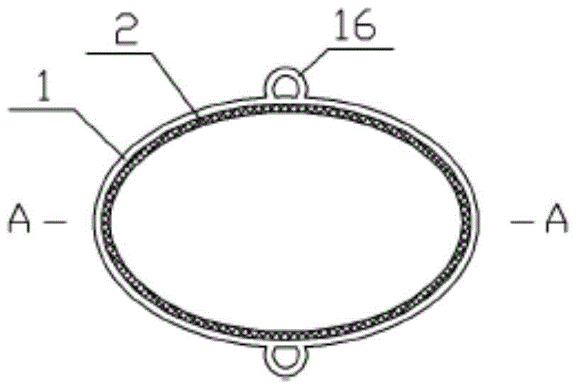
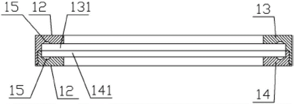
[0012] Such as figure 1 , figure 2 As shown, a seal includes a supporting ring frame 1 and an annular sealing ring 2, an annular groove is provided along the inner wall surface of the supporting ring frame 1, and a ring groove is arranged on the outer surface of the annular sealing ring in the middle of the ring The side ribs 21 snapped by the grooves, and the upper and lower ends 22 of the annular sealing ring extend out of the upper and lower end faces 12 of the supporting ring frame respectively, and the upper and lower end faces of the supporting ring frame are generally planar structures. The length protruding from the upper end surface of the support ring frame is 0.2 to 0.6 times the thickness of the support ring frame, and the length of the annular sealing ring protruding from the lower end surface of the support ring frame is 0.2 to 0.6 times the thickness of the support ring frame. , the outer side ring of the support ring frame is provided with a plurality of pos...


PUM


Abstract

The invention discloses a sealing element which comprises a supporting annular shelf and an annular sealing ring, wherein an annular groove is formed in the inner wall face of the supporting annular frame; an edge rib which is clamped with the annular groove is arranged in the middle of the external side surface of the annular sealing ring; the upper and the lower ends of the annular sealing ring stretch out of the upper and the lower end faces of the supporting annular frame respectively; the supporting annular frame is formed by connecting an upper supporting annular frame with a lower supporting annular frame through a connecting mechanism; an upper annular groove unit and a lower annular groove unit which form the annular groove are arranged on the upper and the lower supporting annular frames respectively; an inner groove face is arranged at the inner end of each of the upper and the lower annular groove units; and a bulge corresponding to the inner groove face is arranged at the end part of the edge rib. The sealing element is simple in structure and convenient to manufacture, can avoid damage caused by overlarge clamping force, and further has the advantages of good convenience in mounting and replacement.

Description

technical field [0001] The present invention relates to seals. Background technique [0002] In various products such as gearboxes, pistons, and oil cylinders, the sealing performance between the shells is one of the important conditions to ensure the normal operation of the products. In the existing structure, sealing rings are usually installed between the shells and then the sealing rings are installed for sealing. , its shortcoming is that it is troublesome to turn the sealing ring into the embedded groove, and it is easy to jump out; another common structure is to directly install a flat sealing ring on the joint end face of the shell to achieve sealing, and its shortcoming is that the sealing is easy to be damaged when the connection is too tight. Swelling is also prone to offset, which affects sealing performance. Contents of the invention [0003] The technical problem to be solved by the present invention is to provide a seal, which is simple in structure, easy t...

Claims


Application Information

Patent Timeline
IPC IPC(8): F16J15/06
CPCF16J15/061
Inventor 苏立锋
Owner WUXI G&Z FLUID EQUIP
Learn More