Air inlet structure for fuel nozzle of gas turbine

A technology for gas turbines and fuel nozzles, applied in combustion chambers, combustion methods, combustion equipment, etc., can solve problems that affect the safety and reliability of gas turbines, head burnt, nozzles prone to tempering, etc.

Active Publication Date: 2015-03-25
BEIJING HUAQING GAS TURBINE & INTEGRATED GASIFICATION COMBINED CYCLE ENG TECH
View PDF8 Cites 8 Cited by
  • Summary
  • Abstract
  • Description
  • Claims
  • Application Information

AI Technical Summary

Problems solved by technology

[0003] In prior art premixed fuel nozzles, flashback is prone to occur behind the nozzle, requiring a light blow of air to protect the rear of the nozzle
However, the flow rate of light blowing air is often different in different environments and climates. A low flow rate of light blowing air will lead to backfire, resulting in the head being burned, which seriously affects the safety and reliability of the gas turbine.

Method used


Image

  • Air inlet structure for fuel nozzle of gas turbine
  • Air inlet structure for fuel nozzle of gas turbine
  • Air inlet structure for fuel nozzle of gas turbine

Examples


Embodiment 1

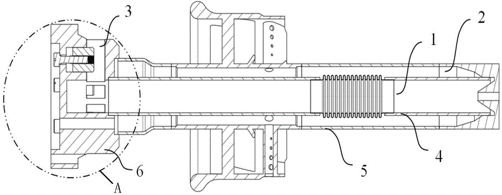
[0029] combine Figure 1 to Figure 3 As shown, the gas turbine fuel nozzle intake structure provided by Embodiment 1 of the present invention includes an inner pipe 4 and an outer pipe 5, the inner pipe 4 is inserted into the outer pipe 5 and relatively fixedly connected, and the inner pipe 4 is defined as a center The air passage 1, the fuel chamber 2 is defined between the inner pipe 4 and the outer pipe 5, and the central air passage 1 and the fuel chamber 2 communicate with each other. The fuel is easier to achieve full combustion, which can effectively prevent backfire at the nozzle outlet and improve the reliability of the nozzle.

[0030] One end of the central air passage 1 is provided with a nozzle suspension flange 6, which is used to fix the inner pipe 4. The nozzle suspension flange 6 of this embodiment is provided with a The air inlet channel 3 that feeds the air, the air inlet channel 3 is preferably a plurality of evenly distributed in the circumferential direc...

Embodiment 2

[0038] The intake structure of a gas turbine fuel nozzle provided in Embodiment 2 is basically the same as the structure of Embodiment 1, and the similarities will not be described again. The difference lies in:

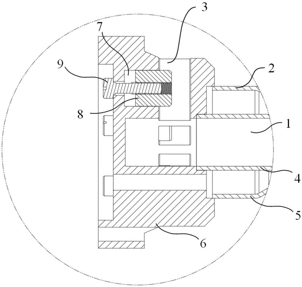
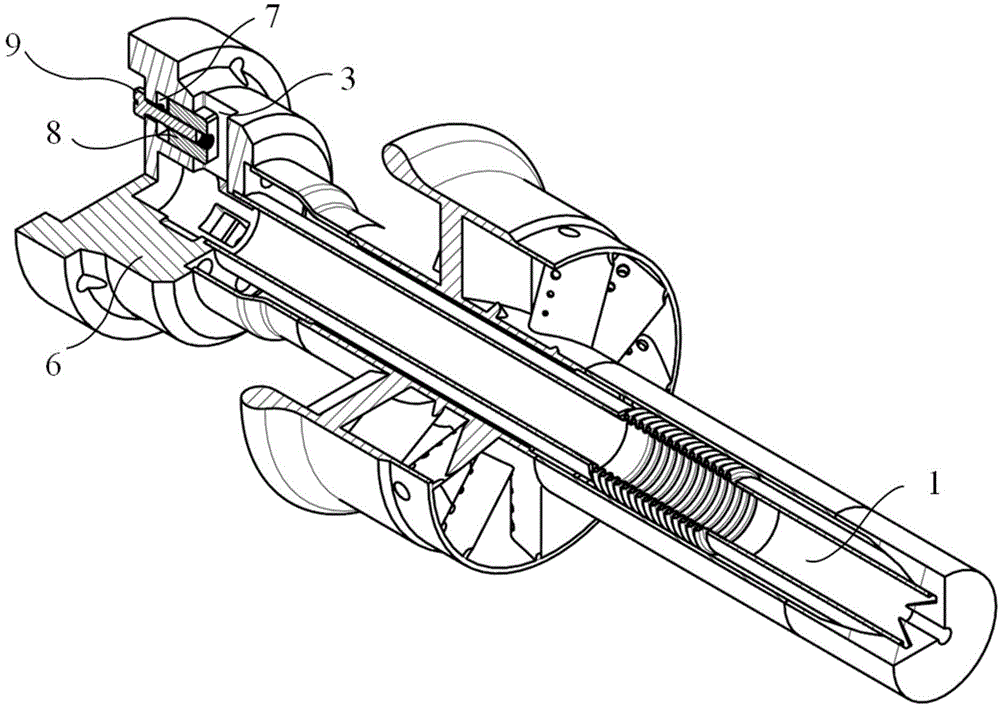
[0039] combine Figure 4 and Figure 5As shown, one end of the adjustment rod 9 is threadedly connected with the shaft hole, the other end of the adjustment rod 9 is against one side of the flow limiting block 8, and the other side of the flow limiting block 8 and the side wall of the air inlet channel 3 are provided. There is an elastic part, and the elastic part can be a spring. The adjusting rod 9 pushes the current limiting block 8 forward through the cooperation with the shaft hole, and the current limiting block 8 is returned by the elastic force of the elastic part; if other elastic parts are adopted, the elastic part The width should be smaller than the width of the air inlet channel 3, so as not to have an excessive impact on the intake air; compared with E...


PUM


Abstract

The invention relates to the technical field of gas turbines, and provides an air inlet structure for a fuel nozzle of a gas turbine. The air inlet structure comprises a center air channel and a fuel cavity which are communicated with each other, and the center air channel is used for connecting the air into the fuel cavity. A nozzle hanging flange is arranged at one end of the center air channel, the nozzle hanging flange is provided with a plurality of air inlet channels used for connecting the air into the center air channel, and the air inlet channels are evenly distributed in the circumferential direction of the nozzle hanging flange. Each air inlet channel is provided with an adjusting mechanism, and each adjusting mechanism is used for limiting the size of the minimum flow area of the corresponding air inlet channel. Each adjusting rod can be adjusted independently, the speed distribution of the air on the head portion of a combustion chamber is effectively improved, the mixing effect of fuel and the air is improved, hence, tempering can be effectively prevented from happening at a nozzle outlet, and the reliability of the nozzle is improved. The air flow can be steplessly adjusted, stepless speed change of the air turbine can also be achieved, and the fuel can be fully burnt ultimately.

Description

technical field [0001] The invention relates to the technical field of gas turbines, in particular to an air intake structure of a gas turbine fuel nozzle. Background technique [0002] The traditional gas turbine combustor adopts diffusion combustion technology. Due to the local high temperature in the combustion chamber, the pollutant emissions, especially the nitrogen oxide emissions, are relatively high. The combustor using premixed combustion for gas turbine power generation technology is one of the clean energy technologies, which can effectively reduce pollutant emissions while meeting the power generation load requirements. Among them, the design of the gas turbine combustor nozzle is particularly important for organizing combustion and reducing pollutant emissions. [0003] In the prior art of premixed fuel nozzles, the rear of the nozzle is prone to flashback, so a light blow of air is required to protect the rear of the nozzle. However, the flow rate of light bl...

Claims


Application Information

Patent Timeline
Patent Type & Authority Applications(China)
IPC IPC(8): F23R3/04F23R3/26
Inventor 刘小龙张珊珊查筱晨张龙
Owner BEIJING HUAQING GAS TURBINE & INTEGRATED GASIFICATION COMBINED CYCLE ENG TECH
Why Eureka
Try Eureka