Light emitting device and projection device

A light-emitting device and a light-splitting device technology, applied in the field of light sources, can solve problems such as restricting the prospect of laser light source display

Inactive Publication Date: 2015-03-25
杨毅
View PDF10 Cites 0 Cited by
  • Summary
  • Abstract
  • Description
  • Claims
  • Application Information

AI Technical Summary

Problems solved by technology

This problem has not been well resolved, which also restricts the prospect of laser light source for display

Method used


Image

  • Light emitting device and projection device
  • Light emitting device and projection device
  • Light emitting device and projection device

Examples


Embodiment Construction

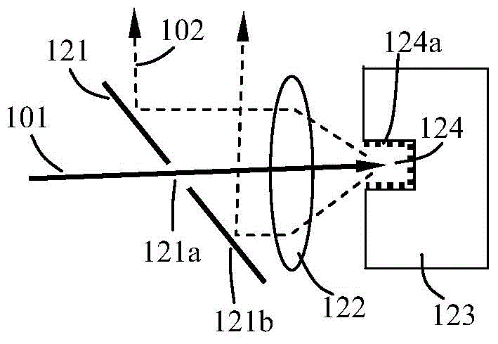
[0014] The first embodiment of the light-emitting device of the present invention is Figure 1A shown. The light emitting device includes a laser light source (not shown in the figure) and a scattering reflection device 123, and the scattering reflection device 123 includes at least one depression 124, and the inner wall 124a of the depression 124 has a scattering reflection property. The light emitting device further includes a light splitting device 121, and the light splitting surface of the light splitting device includes two regions, a transmissive region 121a and a reflective region 121b. Wherein, the laser light 101 emitted by the laser light source passes through the transmissive area 121a of the spectroscopic device and is incident in at least one depression 124 of the scattering reflection device. And be reflected by it to form the outgoing light 102 of the light emitting device.

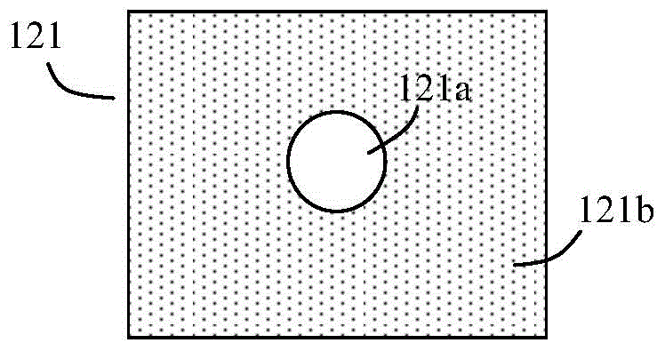
[0015] Figure 1B It is a front view of the spectroscopic device 121. It can be seen...


PUM


Abstract

The invention provides a light emitting device and a projection device. The light emitting device comprises a laser source and a scattering and reflection device. The scattering and reflection device comprises at least one pit, the inner wall of the pit has scattering and reflection attributes. The light emitting device further comprises a light splitting device, and the light splitting face of the light splitting device comprises two areas, namely a transmission area and a reflection area. Laser emitted by the laser source is transmitted to the transmission area of the light splitting device and comes into the at least one pit of the scattering and reflection device, laser is scattered and reflected in the pit and then is emitted, and most of the laser comes into the reflection area of the light splitting device and then is emitted to form emergent light of the light emitting device. By means of the light emitting device, the laser is scattered and reflected on the inner wall of the pit for many times so that the laser can be fully mixed and coherence can be eliminated. Meanwhile, difference of the incoming laser and the scattered laser in terms of alignment is used so that the scattered laser can be separated from a light path to form emitted light.

Description

technical field [0001] The invention relates to the field of light sources, in particular to a light emitting device and a projection device using the light emitting device. Background technique [0002] At present, the application of laser light source has been paid more and more attention. Laser has the advantages of high brightness and long life, but its problem is that it has strong coherence, and when it is used for display, it is manifested as a serious speckle problem. In order to eliminate speckle, the coherence of laser must be eliminated, but as one of the essential properties of laser, the elimination of coherence is very difficult, often at the cost of sacrificing efficiency. This problem has not been well resolved, which also restricts the prospect of laser light source for display. Contents of the invention [0003] The present invention proposes a light-emitting device, including a laser light source and a scattering reflection device, the scattering r...

Claims


Application Information

Patent Timeline
Patent Type & Authority Applications(China)
IPC IPC(8): G03B21/20G02B27/48
CPCG03B21/2066G02B27/48G03B21/2006
Inventor 杨毅
Owner 杨毅
Why Eureka
Try Eureka