Time domain integration sampling method and sampling circuit
A technology of time-domain integration and sampling circuits, which is applied to electrical components, electrical signal transmission systems, signal transmission systems, etc., can solve problems such as increasing the difficulty of hardware implementation, and achieve the effect of reducing the difficulty of implementation and reducing sampling data
- Summary
- Abstract
- Description
- Claims
- Application Information
AI Technical Summary
Problems solved by technology
Method used
Image
Examples
Embodiment 1
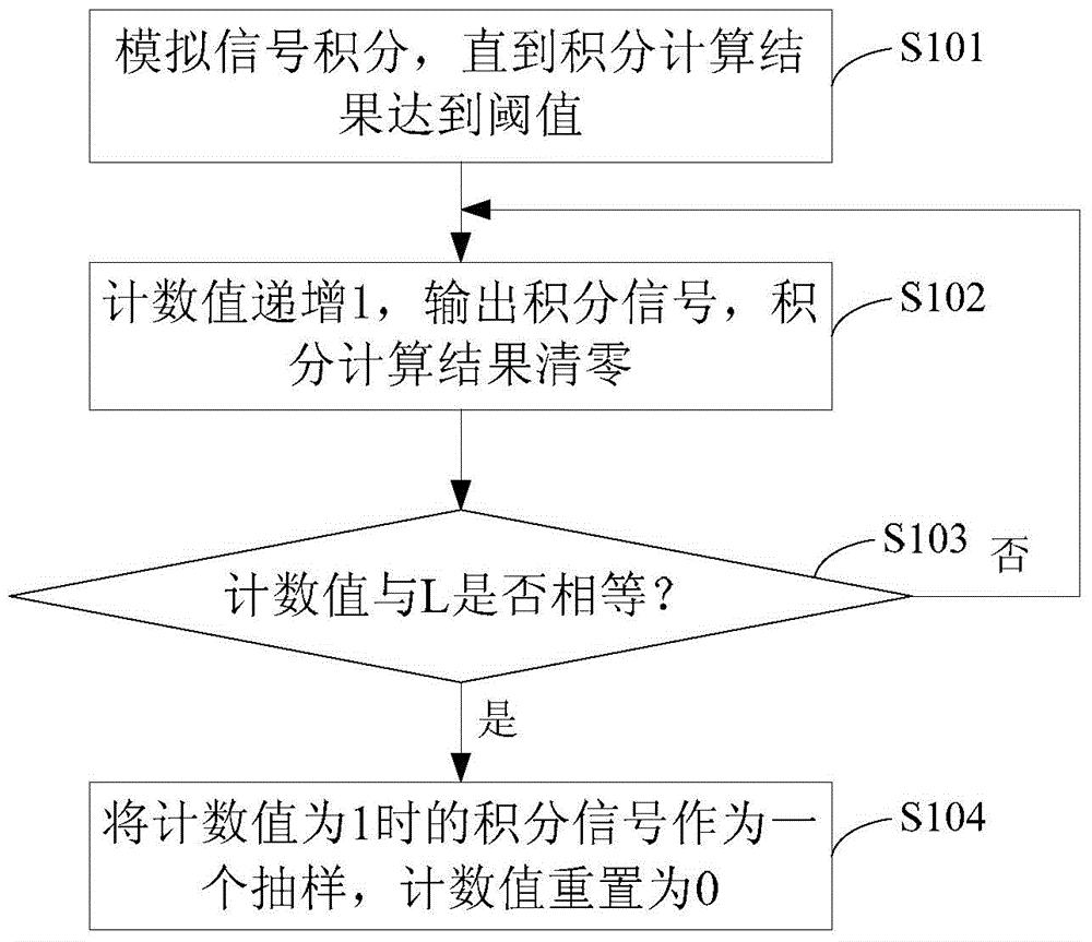
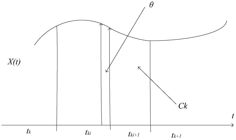
[0041] Embodiment 1 of the present invention provides a time-domain integral sampling method, such as figure 1 with image 3 As shown, the method includes the following steps:
[0042] Step S101: performing time-domain integration on the analog signal to be sampled until the result of the integral calculation reaches a preset threshold;
[0043] In this embodiment, the analog signal to be sampled has the following characteristics, assuming that the analog signal is x(t), it can be expressed as N basic functions in t∈[0, T] linear combination of
[0044]
[0045] Among them, =(X 1 ,...,X N ) T is a coefficient vector; and X has only S non-zero elements and S That is, the analog signal is compressible or K-sparse. In natural signals, most signals are compressible signals, and the sampling method of this embodiment can be used for signal sampling and acquisition.
[0046] In this embodiment, the integration time is not set, but the threshold for integration calculation...
Embodiment 2
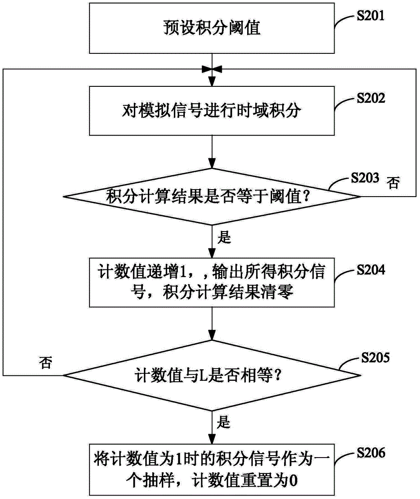
[0072] Embodiment 2 of the present invention provides a time-domain integral sampling method, such as figure 2 As shown, the method includes the following steps:
[0073] Step S201: preset integral threshold;
[0074] Step S202: performing time-domain integration on the analog signal to be sampled;
[0075] Step S203: compare the integral calculation result in step S202 with the threshold, if it is less than the threshold, return to step S202; if equal to the threshold, execute step S204;
[0076] Step S204: increment the count value by 1, and output the integral signal obtained in step S202, and clear the integral calculation result; the initial value of the count value is 0, and the maximum value of the count value is L;
[0077] Step S205: compare the count value obtained in step S204 with the maximum value L, if the count value is less than L, return to step S202; if the count value is equal to L, execute step S206;
[0078] Step S206: Take the integrated signal output...
Embodiment 3
[0081] Embodiment 3 of the present invention provides a time-domain integral sampling circuit, such as Figure 4 As shown, the circuit includes: integration unit 1 , comparator 2 , counter 3 , D flip-flop 4 , or logic circuit 5 and delay circuit 6 .
[0082] Wherein, the integral unit 1 receives the analog signal to be sampled, and outputs an integral signal after the integral operation; the comparator 2 is connected with the integral unit 1, and a reference value is provided in the comparator 2, and the comparator 2 receives the integral signal output by the integral unit 1, The integral signal is compared with the reference value, and when the comparison result is equal, the integral signal is output at the output terminal, and an identification signal is generated; the counter 3 is connected with the comparator 2, and the counter 3 receives the identification signal output by the comparator 2, and the counter 3 A reference value is preset, and when the number of received id...
PUM
 Abstract
Description
Claims
Application Information
 - R&D
- Intellectual Property
- Life Sciences
- Materials
- Tech Scout
- Unparalleled Data Quality
- Higher Quality Content
- 60% Fewer Hallucinations
Browse by: Latest US Patents, China's latest patents, Technical Efficacy Thesaurus, Application Domain, Technology Topic, Popular Technical Reports.
© 2025 PatSnap. All rights reserved.Legal|Privacy policy|Modern Slavery Act Transparency Statement|Sitemap|About US| Contact US: help@patsnap.com


