Check patentability & draft patents in minutes with Patsnap Eureka AI!

Optically variable color image

一种颜色图像、图像的技术,应用在光学可变色图像领域,能够解决多通道光学可变装置限于单色图像或灰度图像等问题

Inactive Publication Date: 2015-03-25
CCL SECURE PTY LTD
View PDF4 Cites 7 Cited by
  • Summary
  • Abstract
  • Description
  • Claims
  • Application Information

AI Technical Summary

Problems solved by technology

However, this multi-channel optically variable device is limited to monochrome or grayscale images

Method used


Image

  • Optically variable color image
  • Optically variable color image
  • Optically variable color image

Examples


Embodiment Construction

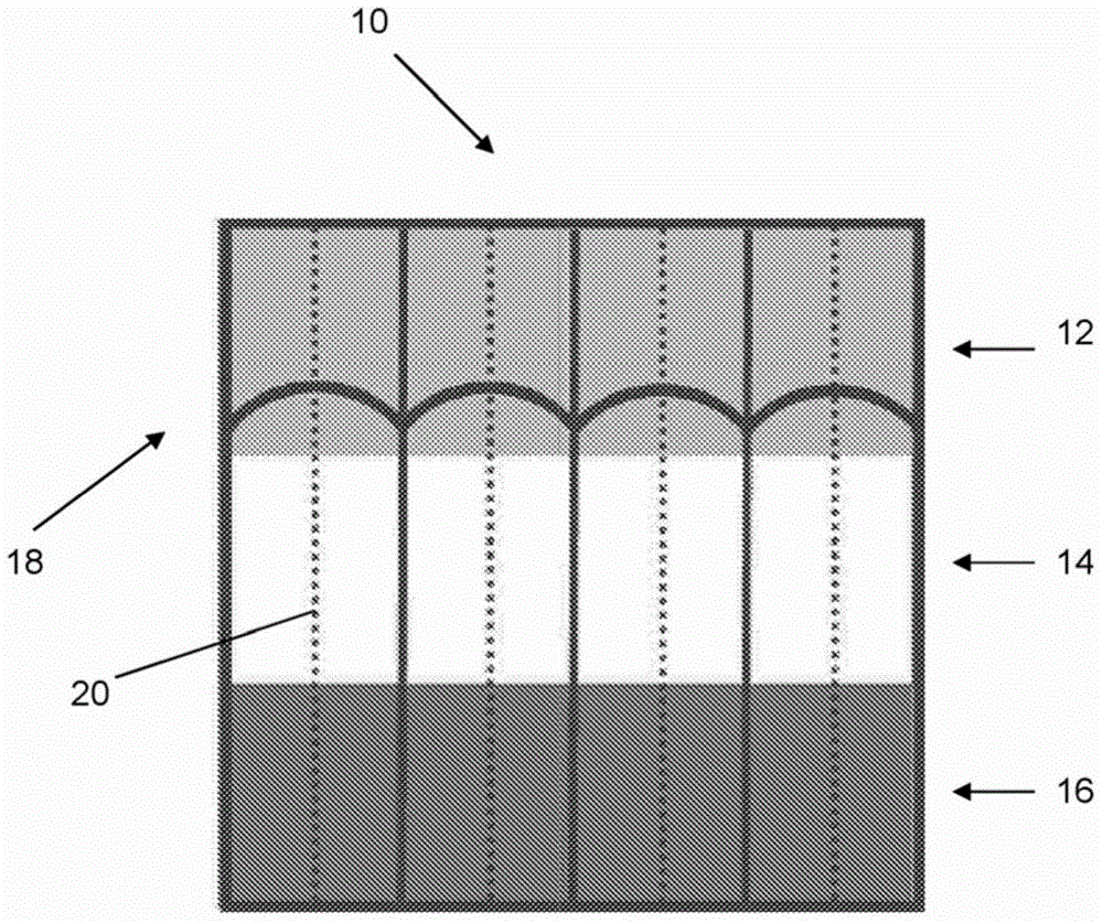
[0086] now refer to figure 1 , shows a portion of a security element with a source image 10 according to a preferred embodiment of the invention. The source image 10 includes three color channels and has three regions, where each region is colored in a primary color and is approximately one-third the area of ​​the source image. The upper zone 12 is colored red, the middle zone 14 is colored green and the lower zone 16 is colored blue. The curved line represents the focusing element 18 , which is a microlens array 18 in this particular embodiment. The dashed lines represent the optical axis 20 of each microlens in the microlens array.

[0087] As an example, the source image 10 may comprise color pixels, where each pixel may have a set of RGB values ​​(r, g, b), where for simplicity the RGB values ​​are normalized from 0 (minimum) to 1 (maximum) .

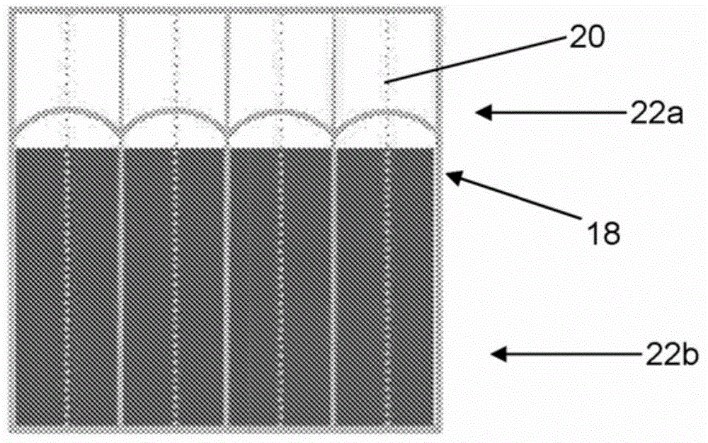
[0088] now refer to Figure 2a , Figure 2b with Figure 2c , shows a grayscale image of each component color channel of th...


PUM


Abstract

A security element including: a plurality of focusing elements, a plurality of image regions where each image region is associated with a focusing element, each image region is printed with at least two layers, the first layer is offset by a first predetermined amount from a reference axis in the image region, the second layer is offset by a second predetermined amount from a reference axis in the image region, each layer being in different colors, and each image region includes at least a first and second sub-region, wherein a first image is formed in a first range of viewing angles from the first sub-region and a second image is formed in a second range of viewing angles from the second sub-region.

Description

technical field [0001] The present invention relates to optically variable elements for security and decorative purposes and methods for their manufacture. Background technique [0002] It is known to provide optically variable devices in which an array of lenticular (part cylindrical) lenses is focused on an object plane with sets of interleaved image elements. Each set of image elements belongs to a different image such that a different image becomes visible when a person viewing the device changes the viewing angle. Optically variable devices are also known comprising two-dimensional arrays of non-cylindrical lenses, in particular spherical microlenses. [0003] In security documents, and especially flexible security documents like banknotes, it may be desirable to minimize the thickness of the lenticular lenses or microlens arrays. In order to produce these security documents, the microlens or lenticular lens array would have to have a relatively small focal length, an...

Claims


Application Information

Patent Timeline
Patent Type & Authority Applications(China)
IPC IPC(8): G02B3/00G07D7/20B42D25/20B42D25/36B42D25/45
CPCB41M3/14B42D15/00G02B3/00G07D7/00G07D7/12G02B3/0056B42D25/29B42D25/45B42D25/324B42D25/351B42D25/328B41M3/148B42D25/21B42D25/24B42D25/405B42D25/30G02B27/123G02B27/1086G02B27/126G02B3/005
Inventor 卡尔洛·伊万·约利奇
Owner CCL SECURE PTY LTD
Features
  • R&D
  • Intellectual Property
  • Life Sciences
  • Materials
  • Tech Scout
  • Unparalleled Data Quality
  • Higher Quality Content
  • 60% Fewer Hallucinations
Learn More